
Print Profiles
Lightweight aircraft printing without the guesswork.
WUDFLY aircraft use foaming LW-PLA for the main airframe, with PETG structural parts and thin TPU hinges where specified. The shared profile pack and the notes below provide the tested material and process baseline used across the current aircraft range.
Use this page for material and process settings. The files supplied with each aircraft remain the authority for orientation, painted supports, modifiers, material call-outs and reference part masses.
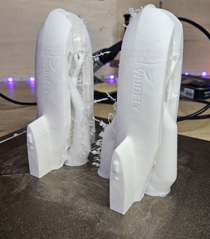
Check strings, blobs, support marks, fitment and mass before assembly. Clean interfaces and consistent structure matter more than cosmetic perfection.
Recommended setup
The supplied WUDFLY profiles were developed using a Bambu Lab X1 Carbon and ColorFabb LW-PLA. Closely related Bambu printers can use them as a strong starting point. Other capable FDM printers should be calibrated and checked against the reference masses supplied with the aircraft.
Why mass matters
Every WUDFLY aircraft has a target printed mass. Small variations are normal, but consistently heavy parts usually mean that LW-PLA flow, foaming behaviour or the slicer profile needs adjustment.
Not vase mode
WUDFLY aircraft use conventionally sliced parts rather than vase mode. This allows local reinforcement, low infill where required, controlled supports and more freedom in how each component is designed.
Fitment first
Remove strings, blobs and support marks where needed, but do not chase cosmetic perfection. The goal is clean fitment, correct alignment and parts that assemble without unnecessary force.
Use the supplied project files
The shared profile controls the printing baseline. Orientation, painted supports, material changes and local modifiers are aircraft-specific and are supplied with the relevant aircraft package.
Developed with ColorFabb LW-PLA
All published WUDFLY airframe masses and reference part weights are based on ColorFabb LW-PLA. It is the filament used throughout development, printing and flight testing, so it gives builders the closest starting point to the aircraft shown on the site.
WUDFLY is not affiliated with or sponsored by ColorFabb. Other foaming LW-PLA filaments may work, but expansion, density, extrusion behaviour and finished part mass can vary and should be calibrated independently.
Printer compatibility
Compatibility should describe how the printer has been validated, not imply that every machine has been personally tested.
Bambu Lab X1 Carbon
The development printer used for the supplied profiles and published reference results.
Bambu P1S / P1P
Closely related hardware and slicer workflow. Verify first-layer behaviour and finished part mass.
Calibrate and verify
Use the baseline values below as a target, then compare mass, fit and surface quality with the aircraft documentation.
LW-PLA baseline settings
These are the core values used for the WUDFLY LW-PLA profile. Treat them as a reference point, not a universal guarantee. Different printers, nozzles, filament batches and environments may need calibration.
Material
- Filament: foaming LW-PLA
- Diameter: 1.75 mm
- Density: approx. 0.6 g/cm³
- Flow ratio: 0.48
- Max volumetric speed: 10 mm³/s
Temperature
- Nozzle: 250°C
- Initial layer: 250°C
- Build plate: 55°C
- Initial bed temp: 55°C
- Plate types: cool / hot / textured plate at 55°C
Cooling
- Fan off: first layer
- Fan range: 20–30%
- Aux fan: 20%
- Overhang fan: enabled
- Overhang fan speed: 100%
Process
- Layer height: 0.24 mm
- Line width: 0.4 mm
- Infill: 3% gyroid for most LW-PLA parts
- Speeds: around 50 mm/s for main print moves
- Supports: disabled by default, painted where required
Aircraft-specific LW-PLA notes
Orientation and supports vary between aircraft. The project files supplied with each design remain the final reference. The examples below preserve the useful preparation guidance from the original BANDIT profile page.
-
Front fuselage:
Support the front FC bay and nose overhangs. Block supports from the fuselage tab slots and magnet recesses. -
Rear fuselage:
Support the wire channels, GPS/RX bays and rear FC bay areas. Exclude the marked no-support areas. -
Wing panels:
Support the overhanging surfaces inside the servo pocket. Do not generate supports in the servo slot or wing root. -
Elevons:
Print vertically on the flat leading-edge surface. Support the angled underside section. Use the higher elevon infill setting supplied in the project file. -
Camera mount:
Orient around 45° to the build plate. Paint supports along the contact edges and across the overhanging top surface. -
Canopy front / rear:
Stand the part on its leg and paint supports only on the overhanging sections shown in the manual. -
Small LW-PLA parts:
Use the supplied orientation for FC mounts, camera support and servo covers. Keep the parts clean and light. -
Cleanup:
Remove strings, blobs and support marks. Focus on fitment, not cosmetic perfection. Parts should close without large gaps.
PETG structural parts
PETG is used where extra toughness, heat resistance or structural reliability is needed. Follow the material call-outs supplied with the individual aircraft; the motor mount is a common example because it sees motor heat and flight loads.
Motor mount
- Material: PETG recommended where specified
- PLA: not recommended for heat-loaded mounts
- Reason: heat and mechanical load
- Check: fastener holes and layer adhesion
Bulkheads
- Material: PETG where specified
- Structure: use the supplied project settings
- Goal: strength without unnecessary mass
Small PETG parts
- Examples: tabs, horns, pins and latches
- Goal: reliable fasteners and wear areas
- Check: clean walls and good layer adhesion
Print quality
- Avoid: weak layer bonding
- Avoid: excessive stringing
- Check: fastener fit before final assembly
TPU elevon hinges
Where supplied, the elevon hinges are printed as extremely thin TPU strips. Bed cleanliness and careful first-layer handling matter more than aggressive slicer settings.
Geometry
- Thickness: 0.2 mm
- Print style: single layer on the bed
- Orientation: square to the bed axes
Bed prep
- Plate: clean PEI or engineering plate
- Glue stick: thin, even layer
- Purpose: adhesion and release layer
Printing
- First layer: print slowly
- Do not rush: long hinge lines need clean movement
- Remove: purge lines or flow calibration that cross the hinge
Removal
- Cool first: let the plate cool
- Remove carefully: avoid stretching the strip
- Inspect: clean edges and consistent width
Before assembly
Printed aircraft parts do not need to look perfect, but they do need to be light, aligned and structurally sound.
- Weigh your parts: compare printed part masses with the BOM and reference masses supplied for the aircraft.
- Check foaming behaviour: if most parts are heavy, recalibrate LW-PLA flow and temperature.
- Dry fit first: tabs, slots, magnets, wing roots and canopy joints should seat without force.
- Clean only what matters: remove strings, support marks and blobs that affect fitment.
- Keep sanding minimal: protect yourself from dust, especially when carbon fibre is involved.
- Use the aircraft documentation: the shared profile notes do not replace the project files, BOM and build guide supplied with the aircraft.
Download the profile pack
Use the WUDFLY pack as the tested starting point for the shared lightweight-aircraft workflow. For other printers or filaments, use the published values as a calibration target and confirm the final part weights before assembly.
Profile status
This is the current public WUDFLY profile pack for the aircraft range. Aircraft-specific orientation, supports and modifiers remain in each aircraft package.