
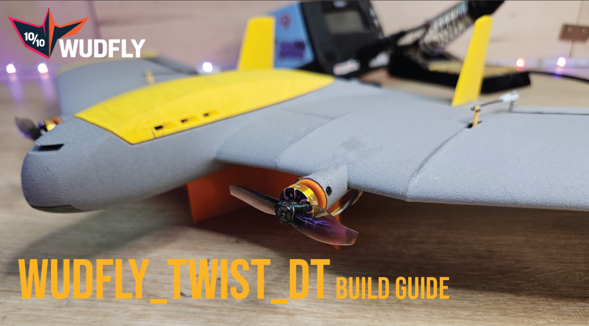
Twisted Build Guide
A practical assembly guide for the Twisted airframe.
This guide covers the printed parts, electronics installation, wiring, motor pylons, elevon hinge setup, and basic build checks. Clean the parts, dry-fit everything, test the electronics while the aircraft is still open, then move into final assembly.
Printing notes.
Print the parts, then remove strings, burrs, blobs, support remnants, and anything else that stops the parts fitting cleanly. Sand as little as possible. If something does not fit, first look for a small print defect or support material.
Sanding printed plastic creates fine dust and microplastics. If you do need to sand anything, do it in a way that keeps the dust contained. Working outside is a good idea, and it is worth wearing sensible PPE such as a dust mask or respirator and eye protection.
I sand and vacuum the parts and sandpaper after each part is prepared to reduce loose dust. The point is not to make the parts perfectly polished; it is just to clean up the small areas that actually need attention.
As a normal starting point, print the fuselage parts at 4% gyroid infill, the wing sections at 3% gyroid infill, and the elevons at 4–10% infill. The exact elevon infill can be adjusted depending on stiffness, weight, and balance.
The battery access part can be used as a small balance-trim part. If your aircraft needs the CG further forward, it can be printed with higher infill or in a heavier material such as PLA or PETG.
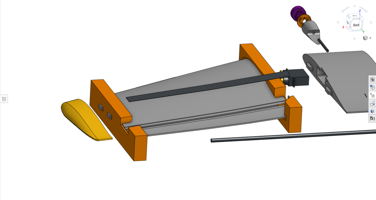
Before gluing, dry-fit the main fuselage, wing sections, servo pockets, ESC tray, motor pylons, and elevon hinge areas. The parts should sit together without being forced.
Public build parts.
Use this as the reference build list. Small substitutions are fine, but check fit, voltage, wiring, current rating, battery position, and CG before flying.
| Count | Part | Mass (g) | Note |
|---|---|---|---|
| 1 | Explorer 750mAh LiHV 2S 80C Battery | 35 | Reference battery |
| 1 | FlyingRC F4 Mini | 6 | Flight controller |
| 2 | Flywoo ROBO 1003 14800KV | 7 | Motors |
| 2 | Gemfan 2015-2 | 1 | Props off during setup |
| 1 | Flywoo Goku BLS 20A 4S V3 4in1 ESC with LED | 5 | Use motor outputs 1 and 2 |
| 1 | iFlight micro step-down BEC module, 2-8S input to 5V/12V output | 2 | Regulated power |
| 2 | DSPOWER 4.3G S002M JR2.54 | 14 | Servos |
| 1 | Radiomaster RP1 | 3 | ELRS receiver |
| 1 | Airframe | 115 | Printed airframe reference |
| Total | Reference build total | 187 | Line items are rounded to whole grams |
Required small hardware
- 1 × 3/1.5 mm carbon rod, 495 mm long
- 6 × tiny cross-head self-tapping screws for holding the motor mounts onto the pylons. These are the same general style as small drone frame screws / motor screws.
Airframe overview
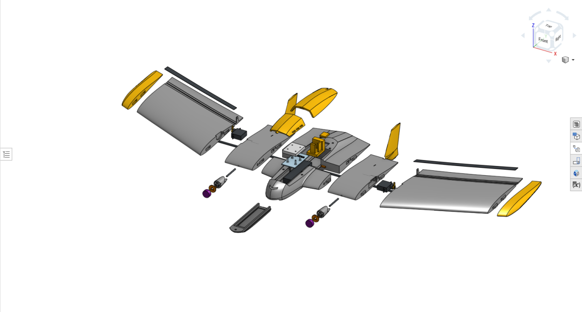
Lay out the printed parts and check that the fuselage sections, wing sections, motor pylon parts, elevon hinge parts, servo mounting areas, and electronics mounting areas are ready.
Do not start permanently gluing things until the electronics route makes sense. The easiest way to avoid problems later is to test-fit the airframe and wiring while everything is still accessible.
ESC tray and battery bulkhead
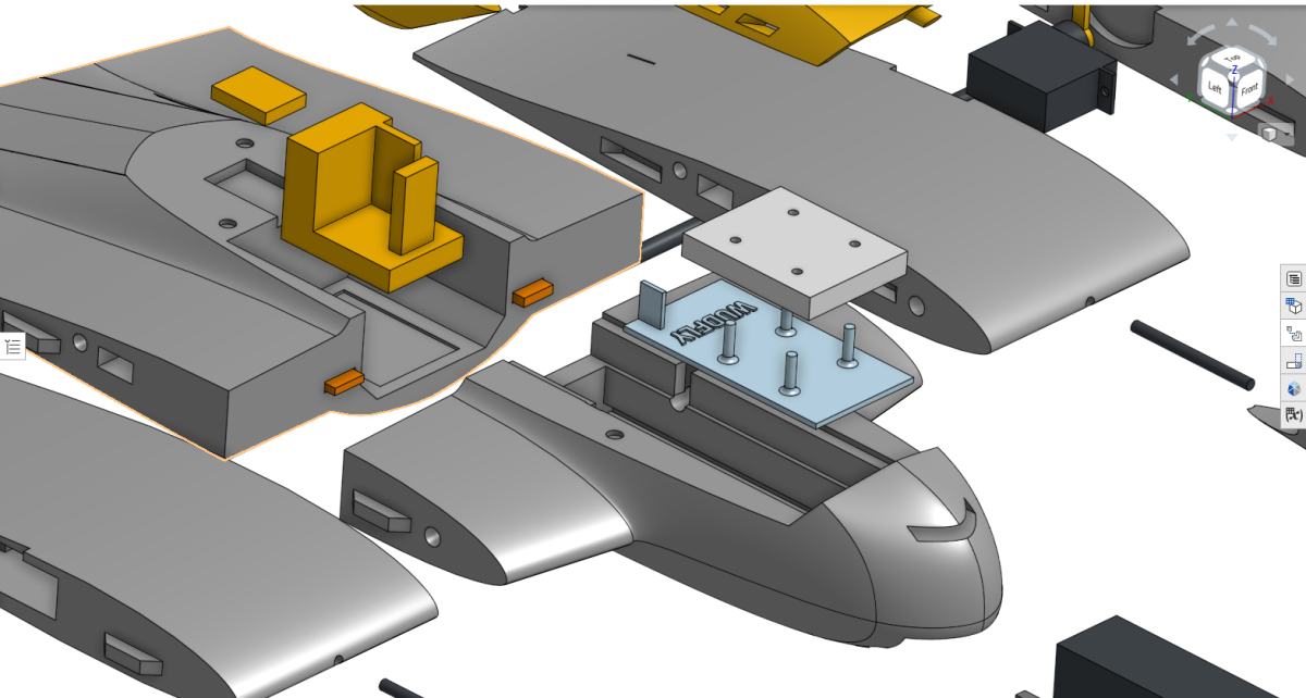
The current ESC is the Flywoo Goku BLS 20A 4S V3 4in1 ESC with LED. Twisted only uses two of the four motor outputs, so use outputs 1 and 2 and leave outputs 3 and 4 unused.
The ESC tray also acts as the battery bulkhead. Add Velcro to the tray before installing it so the Explorer 750mAh 2S LiHV battery can be held securely. A small amount of superglue on the adhesive side of the Velcro helps it stay attached to the printed part.
Glue the bulkhead into the front fuselage using the side rails. Avoid flooding the tray area with glue. Before closing anything, check that the ESC pads, BEC input wires, motor wires, and signal/ground wiring are still accessible.
Flight controller and ELRS receiver
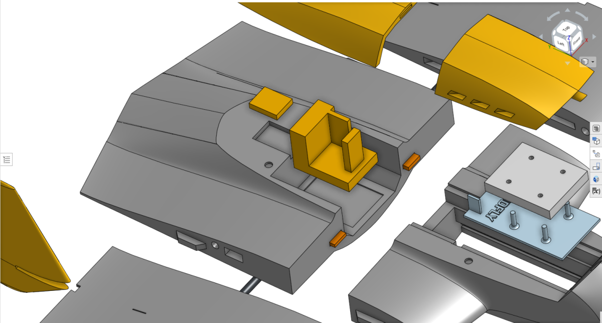
The FlyingRC F4 Mini sits in the rear fuselage section using the printed mount. The Radiomaster RP1 ELRS receiver sits behind it, with the antenna exiting through the rear slot.
The flight controller mount can be fixed with a small amount of superglue. The flight controller and ELRS receiver can be held with a small amount of hot glue if needed. Keep the USB access, servo outputs, motor outputs, BEC input, voltage sense wire, and receiver wiring reachable while setting up.
If hot glue needs to be removed from a retired or damaged airframe, isopropyl alcohol can help debond it, but avoid using it on an airframe you still intend to fly because it can affect LW-PLA.
Servo pockets
The servos must be installed before the outer wing sections are glued on. Clear the servo wire channels first. They may contain small support pieces from printing.
Feed the servo wires through the channels and into the fuselage, then seat the servos in the pockets. Centre both servos before fitting the servo horns. The horns should match side to side as closely as possible.
Avoid fixing an asymmetric horn position later with large trim or midpoint changes. It is cleaner to get the mechanical setup close first.
- Wire channels clear
- Servo wires routed into the fuselage
- Servos seated properly
- Servos centred before horns are fitted
- Servo horns matched left and right
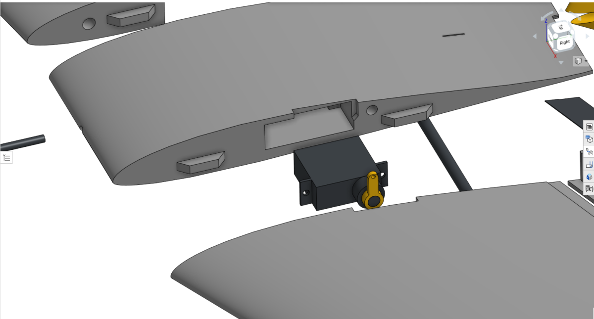
Motor pylons
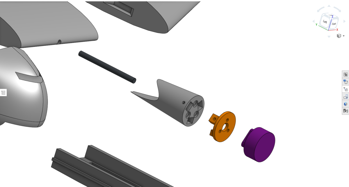
The motor pylon assembly uses the motor, printed motor mount, printed pylon, 30 mm × 2 mm alignment rod section, and three small screws per side.
Prepare the motor wires before final assembly. The motor wires usually need to be extended to reach the ESC cleanly. Around 8–10 cm of extra wire is normally enough. The neatest method is to remove the original motor heat shrink, solder longer wires directly to the motor leads, then insulate the joints with fresh heat shrink.
Attach the motor to the printed motor mount, then slot the mount into the pylon. The motor mount is held onto the pylon with three tiny cross-head self-tapping screws per side. These are the same general style as small drone frame screws or motor screws.
The motor wires should exit underneath the wing, not over the top. The pylon cutout is asymmetric: the longer cutout section belongs on the bottom of the wing.
- Carbon alignment rod fully seated
- Pylon sits flush with the wing
- Motor wires exit underneath the wing
- Motor wire extensions reach the ESC without tension
Elevon hinge jig
This is one of the more delicate parts of the build, so take your time here. The jig holds the wing section while the TPU elevon hinge is glued into the hinge trench. The wing should slide into the jig without being forced.
If the jig fit is too tight, clean up the printed edges gently until the wing sits in place. Do not force it, because that can twist the part or make the hinge line harder to align.
Place the TPU hinge into the hinge trench and check that it follows the line cleanly. Start by tacking the hinge with two small drops of CA glue away from the jig area. This first glue step is only to hold the hinge in position.
Once the tack glue has set, apply CA along the main hinge trench, but do not glue the root and tip areas that are inside the jig yet. Lay the TPU hinge down onto the glued surface without stretching it.
Use the end of a pen or another smooth tool to press the hinge gently into the trench. The hinge should sit flat and follow the line naturally. Thick CA can be useful because it gives a little more working time. Activator can be used if you want the glue to set faster.
After the main hinge section has cured, remove the root and tip jig pieces. Then glue the remaining hinge sections at the root and tip. Because the centre is already fixed, the remaining ends should line up much more easily.
Once everything is dry, turn the wing upside down and trim the excess TPU flush with a sharp blade. Work slowly and avoid pulling on the hinge while trimming.
Electrical setup
Spend a bit of time on this section before soldering. The electrical setup is not complicated, but it is much easier to get right before the airframe is closed.
The basic power path is:
Battery → 4in1 ESC → BEC → Flight controller
The battery connects directly to the ESC battery pads. The BEC input is taken from the same ESC battery pads, and the BEC output provides regulated power to the flight controller and servos.
Main components
- Explorer 750mAh LiHV 2S 80C battery
- Flywoo Goku BLS 20A 4S V3 4in1 ESC with LED
- iFlight micro step-down BEC module
- FlyingRC F4 Mini flight controller
- Radiomaster RP1 ELRS receiver
- Two Flywoo ROBO 1003 14800KV motors
- Two DSPOWER 4.3G servos
Power wiring
- Battery positive and negative → ESC battery pads
- BEC input positive and negative → same ESC battery pads
- BEC output positive and ground → flight controller 5V and ground
The ESC is the only part of this setup that should receive full battery voltage directly. The flight controller, ELRS receiver, and servos are powered through the regulated BEC output.
Motor and signal wiring
- Motor 1 → ESC motor output 1
- Motor 2 → ESC motor output 2
- ESC motor outputs 3 and 4 unused
- Flight controller S1 → ESC control input M1
- Flight controller S2 → ESC control input M2
- Servo 1 → S3
- Servo 2 → S4
- ESC and flight controller must share ground
The shared ground matters. Without a common ground between the ESC and flight controller, the ESC may not read the throttle signals properly.
Voltage sensing
If using voltage sensing, connect the voltage sense wire to the ESC battery positive pad so the flight controller can read main battery voltage. Once wired, battery voltage can be configured in INAV.
Before powering the system
- Check battery polarity before connecting anything.
- Check BEC input polarity.
- Check BEC output voltage with a multimeter before connecting it to the flight controller.
- Check that there are no solder bridges on the ESC pads.
- Check that unused ESC outputs cannot short against anything.
- Keep the propellers removed while testing motor direction and output mapping.