
Spectre Build Guide
A practical assembly guide for the Spectre airframe.
This guide covers printed-part preparation, fuselage and wing assembly, the removable wing-lock system, TPU elevon hinges, electronics installation, control linkages, and the initial mechanical setup.
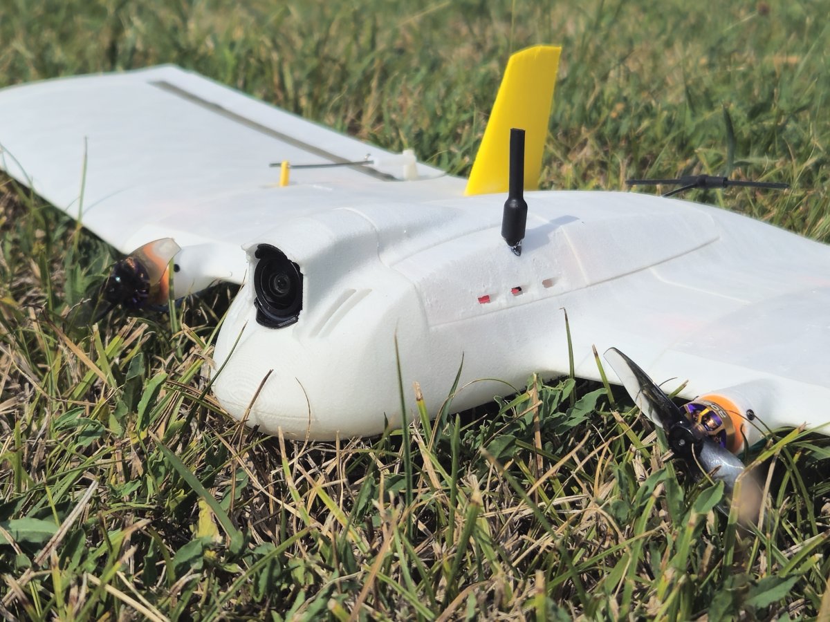
Four phases.
The Spectre manual is organised into four phases: PRINT, BUILD, WIRE and CONFIGURE. The printing, mechanical assembly and reference wiring sections are documented below; the detailed CONFIGURE section follows next.
Public build parts.
Use this as the current reference build. Small substitutions are possible, but check fit, voltage, wiring, current rating, battery position, and CG before flying.
| Count | Part | Mass (g) | Note |
|---|---|---|---|
| 1 | Explorer 1000mAh LiHV 2S 80C Battery | 45.0 | Reference battery |
| 1 | FlyingRC F4 Mini | 6.4 | Flight controller |
| 1 | DJI O4 Wide camera | 8.3 | Reference FPV camera |
| 1 | DJI O4 VTX | 5.23 | Digital video transmitter |
| 2 | Flywoo ROBO 1003 14800KV | 6.6 | Motors |
| 2 | Gemfan 2015-2 | 1.0 | Props off during setup |
| 1 | Flywoo Goku BLS 20A 4S V3 4in1 ESC | 4.5 | Reference ESC |
| 1 | iFlight micro step-down BEC | 1.7 | Regulated power |
| 2 | DSPOWER 4.3G S002M JR2.54 | 13.8 | Servos |
| 1 | RadioMaster RP1 | 3.0 | ELRS receiver |
| 1 | Wiring | 9.0 | Reference allowance |
| 1 | Printed airframe | 110.5 | Reference airframe mass |
Print.
Print the airframe, prepare the functional PETG parts, and check the recommended orientations, infill and support settings before starting the build.
Parts, materials and build plates.
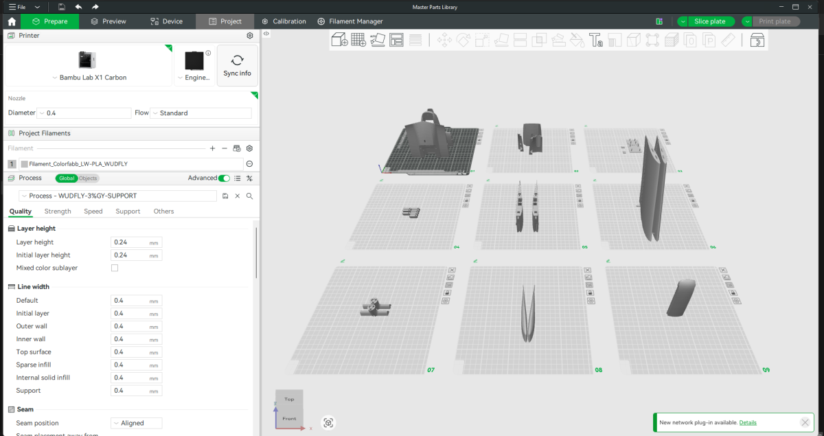
This is the complete Spectre printed-part set arranged across the recommended Bambu Studio build plates.
The majority of the aircraft is printed in ColorFabb LW-PLA. The smaller functional parts and electronics bulkhead are printed in PETG, while the elevon hinges are printed in TPU. All published airframe weights and the reference build are based on ColorFabb LW-PLA.
WUDFLY's current baseline profiles can be downloaded from the Print Profiles page. Use those as the material starting point, then follow the Spectre-specific orientation, infill and support guidance below.
Keep the build plates simple
I normally print the aircraft in roughly the plate groupings shown here. There is usually little benefit in filling every available space on the bed.
More separate parts create more travel movement, which can increase stringing and surface blemishes, particularly with LW-PLA. That normally means more post-processing afterwards.
Smaller, repeatable plates also reduce the amount of the aircraft you lose if one print fails. Wing sections are therefore generally printed in matching pairs, with smaller parts grouped sensibly rather than everything being packed onto a single plate.
The complete Spectre airframe is approximately 12 hours of machine time, so splitting the aircraft across several reliable plates does not create a major printing penalty.
Functional PETG parts
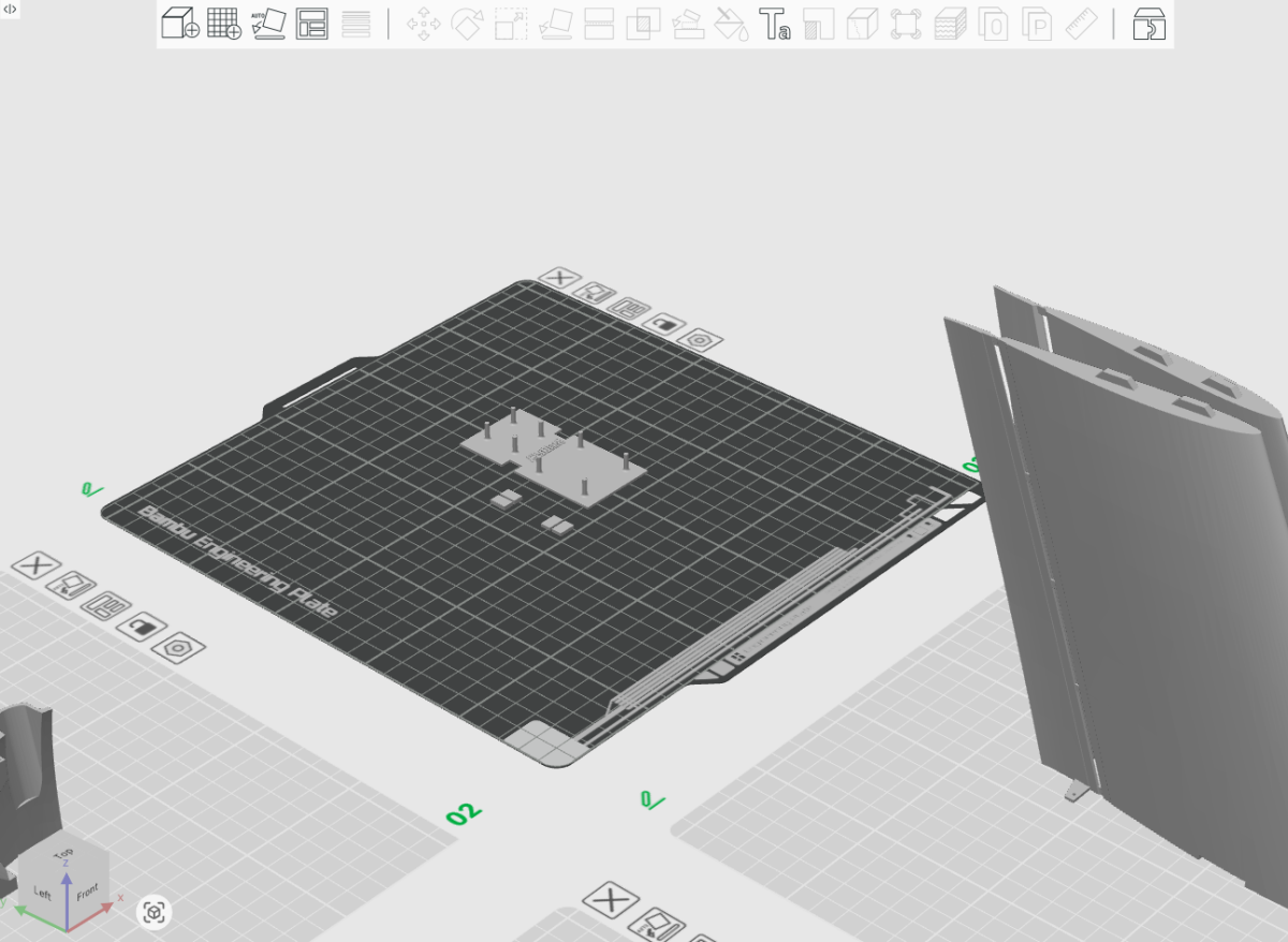
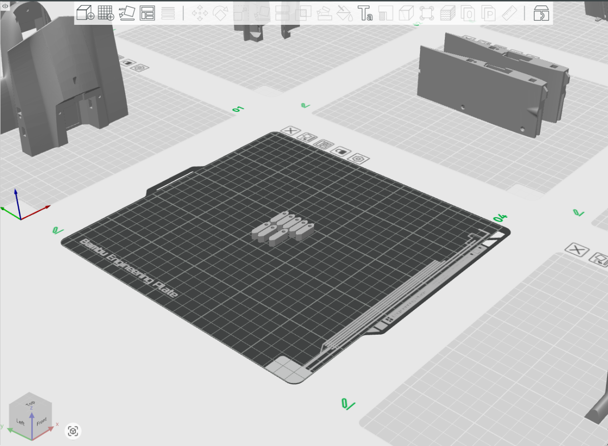
Spectre uses PETG for the electronics bulkhead, joining and locating tabs, wing-lock tabs and motor mounts.
The motor mounts are also PETG parts, although they are not shown in the two plate screenshots above.
Electronics bulkhead
The electronics bulkhead sits directly underneath the electronics package, including the video transmitter. PETG is used here primarily for its better heat resistance. A PLA-based bulkhead may soften or distort when exposed to sustained heat from the VTX.
The bulkhead does not need to be particularly heavy. I use low-percentage grid infill, a relatively low wall count and minimal top and bottom layers.
It is still worth giving the bulkhead enough material to remain comfortably stiff. The battery Velcro attaches to the underside of this bulkhead, so every time the battery is pulled free the load is transferred through the bulkhead into the fuselage. It therefore needs enough stiffness to tolerate repeated battery removal as well as the heat generated by the electronics.
Joining and locating tabs
The smaller PETG tabs can be printed very lightly. Around one wall with minimal top and bottom layers is generally sufficient for these simple parts. They contain very little material, so high infill offers little practical benefit. Clean dimensions and a good fit matter more.
Wing-lock tabs
The wing-lock tabs also do not require high infill in the standard configuration. Their important characteristics are toughness, dimensional accuracy and a clean M3 printed thread.
Before assembly, a steel M3 bolt is run through the printed hole to form and clean the thread before the nylon wing bolts are used.
If you choose to modify the wing locks for heat-set threaded inserts, increase the wall thickness and surrounding material accordingly so the insert has enough PETG to grip.
Motor mounts
The motor mounts should also be printed in PETG. They are not shown on these build-plate screenshots. PETG gives a useful combination of toughness and improved heat resistance for a component mounted directly against the motors.
Front fuselage supports
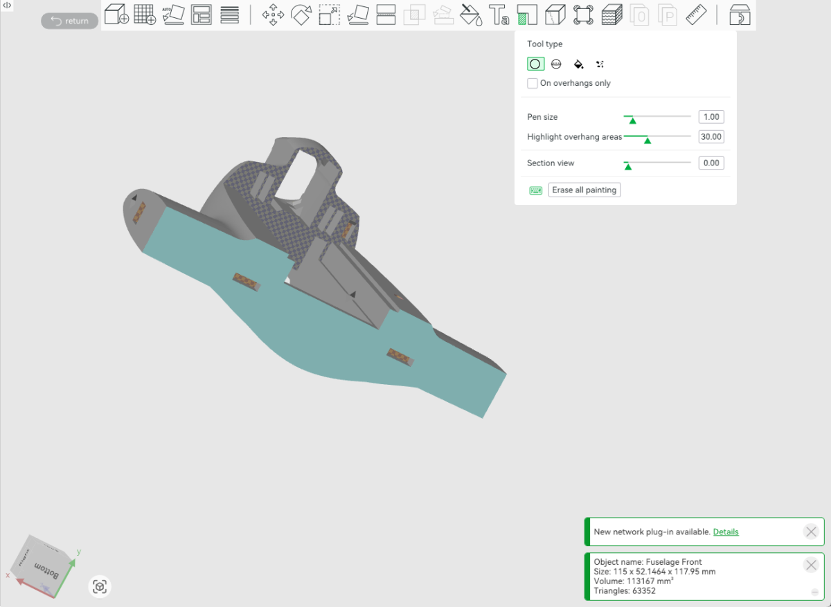
The front fuselage needs support beneath the main unsupported overhang, but several smaller recesses can be printed cleanly without support.
Block support here
- Fuselage joining-tab recesses
- Both wing-lock tab recesses
- Front canopy locating-tab recess
These areas do not need support and are easier to assemble if they are left clean.
Main support area
The important supported area is the large unsupported overhang at the front of the fuselage. This currently requires a fairly substantial support structure.
The geometry may be improved in a future printability update, but the arrangement shown here prints reliably for the current version.
Aft fuselage supports
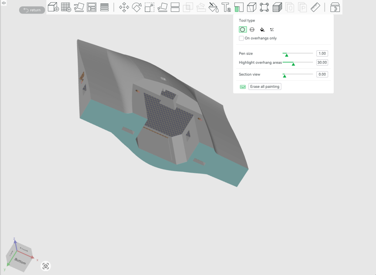
The aft fuselage follows the same support philosophy as the front: support only the geometry that genuinely needs it and keep the smaller locating recesses clear.
Block support here
- Both wing-lock tab recesses
- Joining-tab recesses on the forward mating face
- Fuselage magnet recesses
Keep support here
- Servo-wire channel
- Large aft-fuselage overhang
- Rear of the flight-controller bay
- ELRS receiver pocket area
The servo-wire channel may eventually be enlarged or reshaped so that it prints cleanly without support. There is also scope to reduce support around the electronics area in a future revision.
Front and rear fuselage
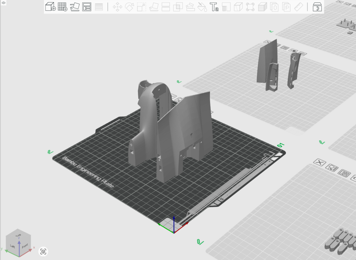
This shows the front and rear fuselage sections positioned on the build plate as they are normally sliced and printed.
The two parts can be placed fairly close together. Keeping them reasonably close reduces unnecessary travel between the parts without crowding the plate.
Fuselage infill
The reference Spectre build uses 4% gyroid infill for both fuselage sections.
This is a good balance between weight and durability, but it is not a hard limit. Spectre has significant margin below 250 g, so the fuselage can be printed heavier if additional durability is preferred.
- 3% gyroid — slightly lighter
- 4% gyroid — reference setup
- Higher infill — more durability at the cost of weight
Keeping a small aircraft light is still useful because lower mass reduces the energy involved when the aircraft hits something or lands badly.
Canopy sections
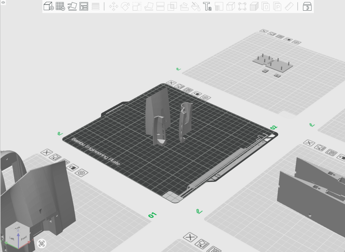
This plate contains the front, rear and side sections of the canopy, orientated as shown.
The canopy sections carry very little structural load, so a lightweight setup works well here and keeps the finished assembly tidy and light.
Outer wing sections
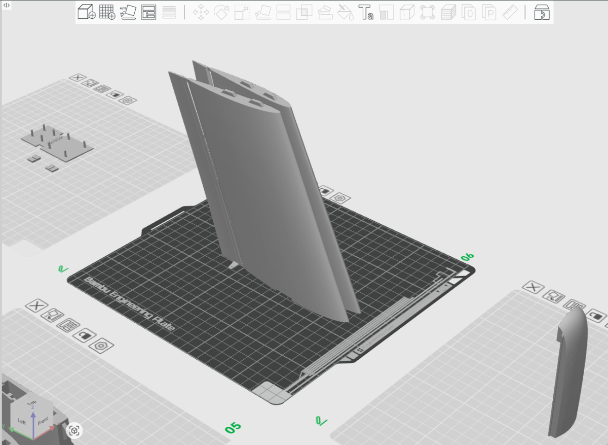
This plate contains the two outer wing sections with their elevons printed in place.
Orientation matters
Arrange the two outer wings with the elevon horns facing outward, away from each other. This also places the recessed TPU hinge areas toward the outside of the build plate.
The purpose is to keep the hinge recess as clean as possible. You do not want Z-seam artefacts, small blobs or local surface swelling concentrated in the area where the TPU hinge will later be bonded.
A clean recessed surface makes it much easier to get the TPU strip sitting flat and consistently bonded along the elevon.
Mirrored parts
For mirrored aircraft components, the STL pack may include a single side only. Use the Mirror function in your slicer to create the matching opposite part.
Inner wing sections
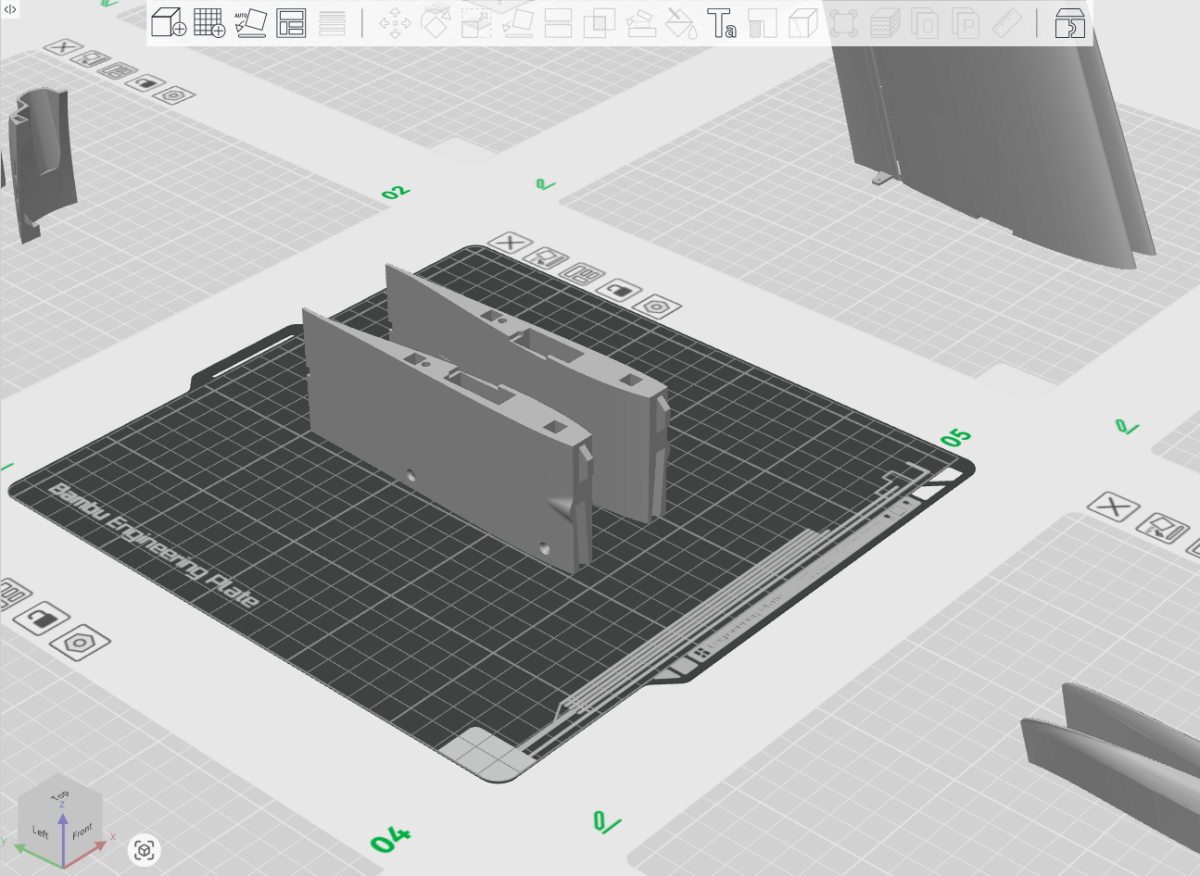
There is nothing unusual required for the inner wing sections. Arrange them on the build plate as shown and print them in the same way as the other main wing structure.
Wingtips
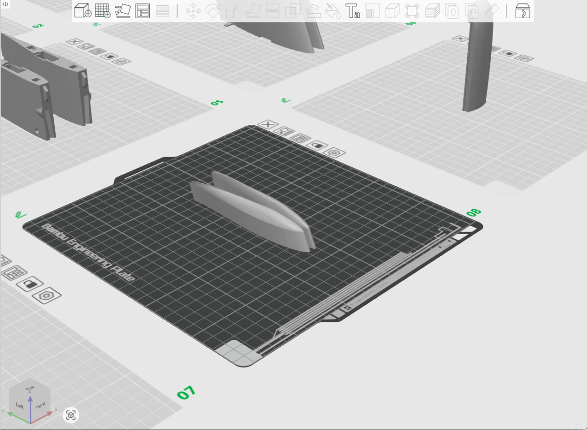
The wingtips are one of the simplest prints in the aircraft. Arrange them as shown and print them normally.
Battery access
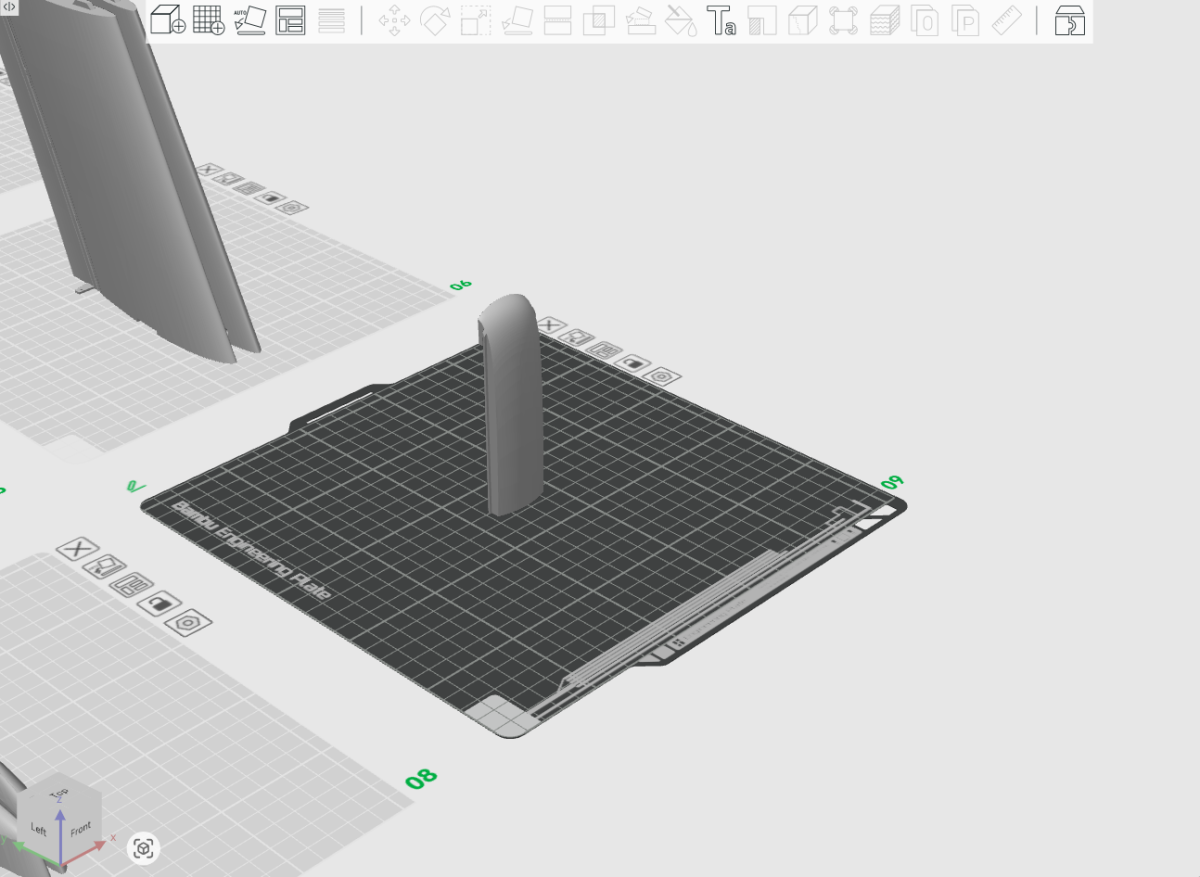
The battery access section prints well in ColorFabb LW-PLA at 3% gyroid infill. Because this part carries relatively little structural load, it is a good place to keep the print light.
Support
The current version uses support beneath the upper overhang of the battery access section.
A future printability update may refine this area to reduce or remove the support requirement. Until then, the current supported orientation is reliable and straightforward to print.
Inner-wing leading edges
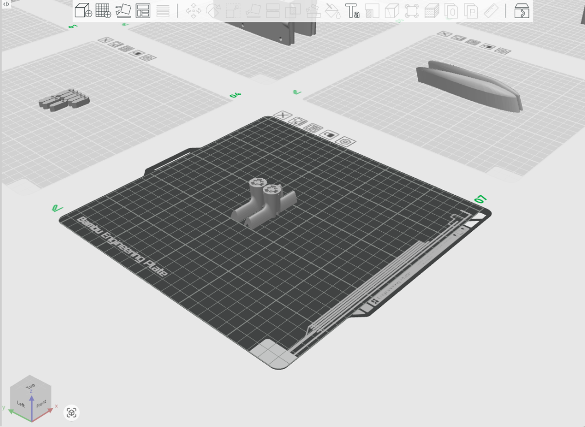
These are the removable inner-wing leading-edge sections that carry the PETG motor mounts.
Unlike most of the wing structure, these parts benefit from a stronger print setup. The motor area can see higher loads during landings or impacts, so a little extra material here is a sensible trade.
Use ColorFabb LW-PLA with at least 10% gyroid infill as a starting point.
Increasing the infill beyond 10% is completely reasonable if you want more durability. Spectre has enough weight margin that adding material here is a sensible trade if it improves the survivability of the motor installation.
A stronger leading-edge section can also help absorb impact loads before they reach the motor hardware.
Because these leading-edge sections are removable and replaceable, they are a sensible place to build in some additional strength.
Build.
Mechanical assembly of the fuselage, wings, canopy, spar, wing locks, TPU hinges and control linkages.
Prepare and join the fuselage
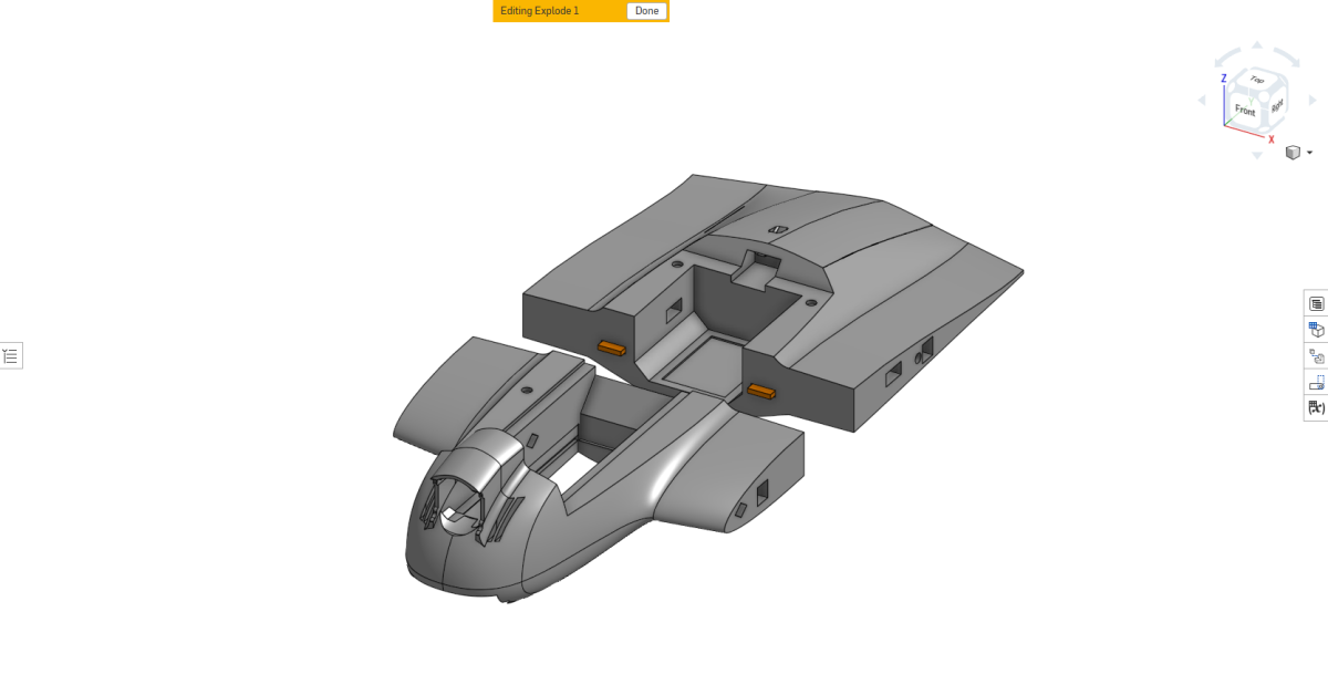
Start with the forward and rear fuselage sections. Remove any loose material, stringing, or support remnants from the surfaces. Pay particular attention to the internal channels, especially the servo-wire channel, which may contain support material.
A small pick or length of carbon-fibre rod works well for clearing the channels. Break the support material away from the channel walls rather than digging the tool into the printed surface.
Prepare the joint
Check both mating faces and remove anything that prevents them sitting together cleanly. Sanding the mating faces should not normally be necessary at this stage. Dry-fit the forward and rear fuselage sections and make sure the joint closes fully and aligns cleanly.
Install the fuselage tabs
Glue the fuselage joining tabs into one fuselage section only. Once fitted, dry-fit the second section again and make sure the complete joint still closes correctly.
Glue the fuselage together
Apply CA glue to the mating faces, bring the two sections together, and hold them correctly aligned until the glue has set. Activator can be used if desired.
Prepare and install the wing lock tabs
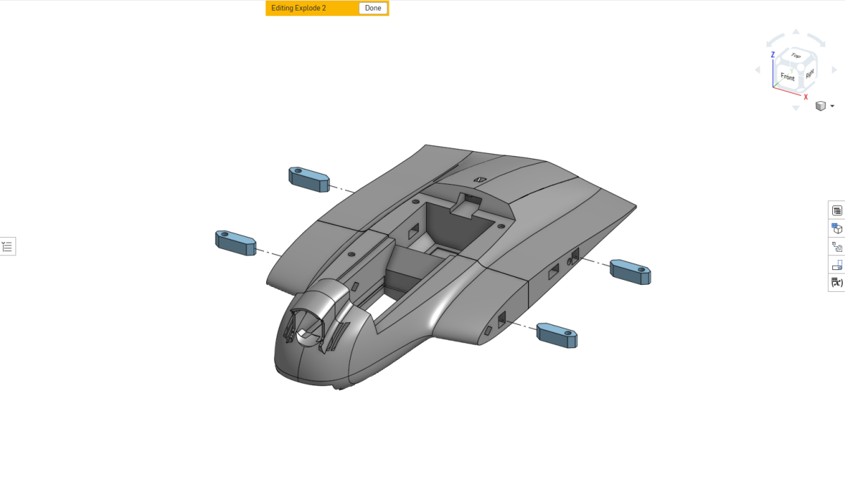
Tap the threads first
Before fitting any wing lock tab to the aircraft, gently run a steel M3 bolt through its threaded hole. The steel bolt forms a much cleaner thread in the PETG than the nylon wing bolts can create themselves.
Run the steel bolt through every tab and remove it again before installation.
Check the fit
The wing lock tabs should not normally require sanding or processing. They are designed to fit tightly in their pockets. Dry-fit each tab and make sure it reaches completely to the bottom of the pocket.
If one face has a noticeably cleaner finish around the threaded hole, orient that face downwards, toward the side from which the nylon wing bolt will enter.
Glue the tabs in place
Apply CA to the fuselage-facing side of each tab and push it fully into its pocket.
Install the electronics bulkhead
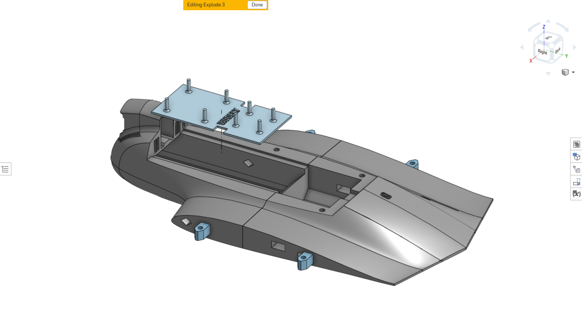
Before printing, choose the bulkhead that matches your electronics package. The default bulkhead is designed for the DJI O4 mounting pattern and a 16 × 16 mm ESC mounting pattern.
If you are using different hardware, select the appropriate bulkhead variant during printing so the mounting holes match your ESC and VTX.
Glue the bulkhead
Apply a small amount of CA into the recessed rails on the upper surface of the fuselage. Press the bulkhead fully into the recess so it sits flush with the surrounding fuselage structure.
Install the fuselage magnets
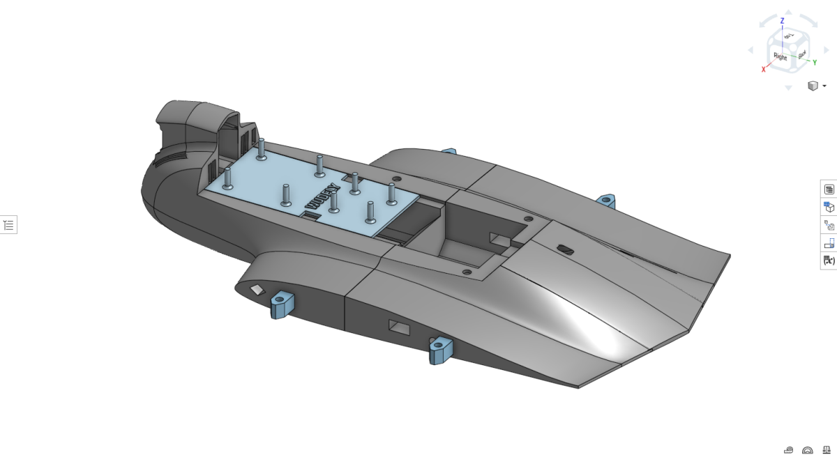
Place a small drop of CA into each magnet recess. Use only enough glue to secure the magnets cleanly.
The easiest method is to leave the magnets attached to the stack. Use the stack to push the end magnet firmly into the recess, hold the installed magnet down with a fingernail, then slide the remaining stack sideways to separate it.
Prepare the battery access
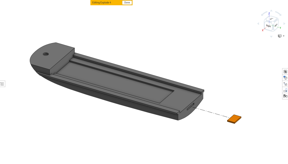
Install the battery access tab
Glue the battery access tab into the aft cutout of the slide-in battery access section. Make sure it is fully seated and correctly aligned before the CA cures.
Install the magnets
Glue the retaining magnets into the corresponding recesses in both the removable battery access section and the lower fuselage.
Once cured, test-fit the battery access and confirm that it slides into place cleanly and is held securely by the magnets.
Assemble the inner wings
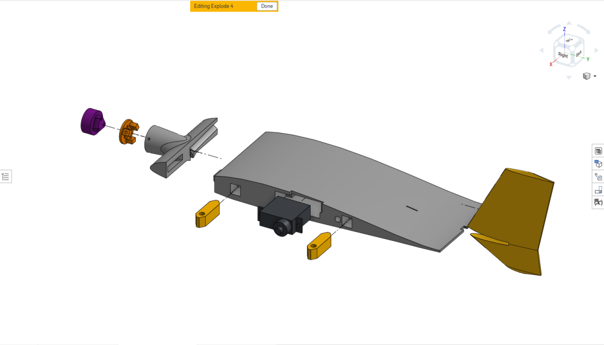
Complete this procedure on one inner wing, then repeat the full process for the opposite side.
Install the wing lock tabs
Install the wing lock tabs using the same preparation method described earlier. The threaded holes must face outwards toward the removable outer wing section.
Install the servo
The reference build uses a DS-Power 4.3 g servo. Feed the servo connector and cable through the hole at the rear of the servo pocket. Seat the servo and secure it using the two supplied screws. Leave the servo horn off for now.
Install the motor
Attach the motor to its motor mount using the supplied motor hardware. Attach the complete mount to the removable leading-edge section using 3 × M1.4 × 5 mm self-tapping screws per motor.
Route the motor wires
Cut the motor wires to a sensible length and ideally braid them together. If not braided, twist the three wires tightly together. Feed the wires through the leading-edge channel.
A small piece of electrical tape can hold them in place, but press the wiring and tape fully down into the V-shaped recess so nothing fouls the mating faces.
Attach the leading edge
For the version shown in these images, apply a small amount of CA to the mating surfaces and bond the leading-edge section to the main inner wing. Avoid excessive glue around the wire channel.
The leading-edge attachment is being revised to use screw retention rather than a permanent glued joint. Updated parts and imagery will follow.
Install the vertical tail
Dry-fit the vertical tail and align it with the reference mark on the wing. It should sit straight with no toe-in and no toe-out. Once correctly aligned, secure it in position.
Assemble the outer wings and TPU elevon hinges
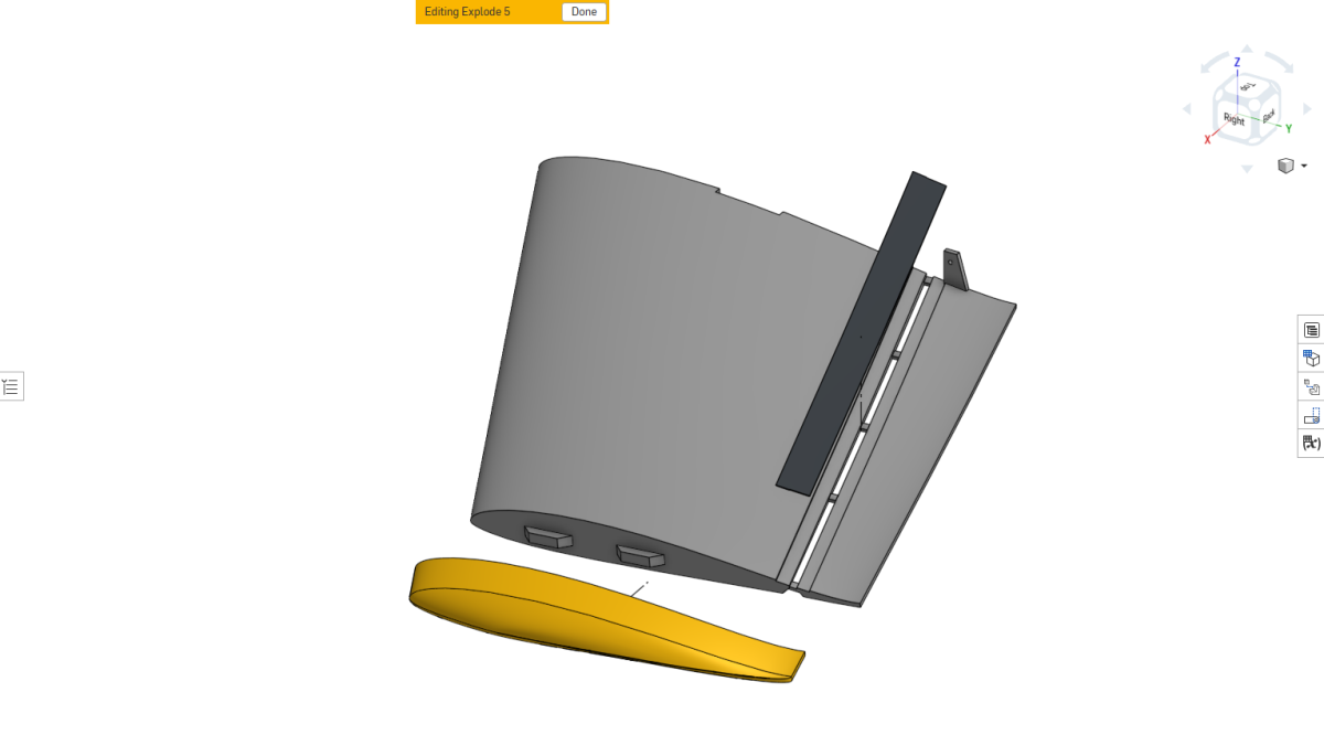
The TPU strip partially laminates the leading edge of the elevon, adding useful stiffness to the light LW-PLA control surface. Spectre's wing is geometrically twisted, so the hinge line does not follow one perfectly straight axis. The flexible TPU strip conforms to that geometry while retaining a clean, flush, lightweight hinge.
Dry-fit the hinge
Place the TPU hinge into its recessed channel and check that it sits flat and flush from one end to the other.
Tack one end first
Around 20–30 mm from one end, place two small dots of CA into the recess. Lay the hinge into position and press it flat until the tack has cured. A small piece of soft foam or sponge works well for applying pressure and absorbing small amounts of excess CA.
Bond the full hinge
Once the initial tack is secure, lift the free end and apply a thin, controlled amount of CA along the remaining channel. Starting from the secured section, progressively lay the hinge down while using the foam with a gentle downward and wiping motion.
Finish the short unbonded section on the opposite side of the initial tack in the same way.
Trim the TPU and free the elevon
Once cured, turn the wing over and trim any TPU protruding beyond the flat end faces using a sharp razor blade.
The elevon is printed in place with several small LW-PLA support tabs. Cut one side of every tab first. Once all tabs are released on the same side, gently open the elevon and remove the remaining material from the opposite side.
Check movement and install the wingtip
Move the elevon through its full range. There should be no clicking, grinding, rubbing, or binding. If necessary, lightly trim or sand the ends of the elevon or the adjacent wing surfaces.
Clear the linkage hole gently with a 2 mm drill bit used by hand or in a pin vise. Dry-fit and attach the wingtip, then check the complete elevon range again.
Assemble the canopy
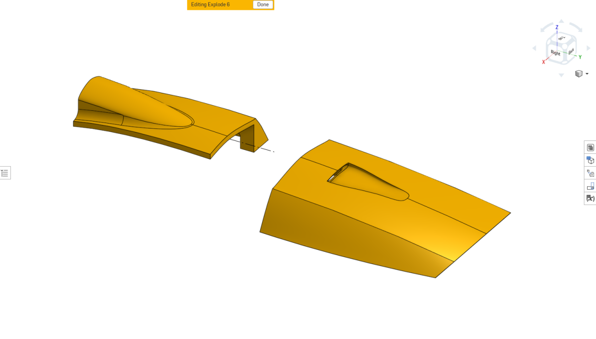
Dry-fit the front and rear canopy sections and check that the mating faces meet cleanly.
Glue the canopy joining tabs into one section, then test-fit the complete canopy again.
Once everything aligns correctly, apply a small amount of CA to the mating faces and join the front and rear canopy sections. Hold the assembly in alignment until the glue has cured.
Install the canopy magnets
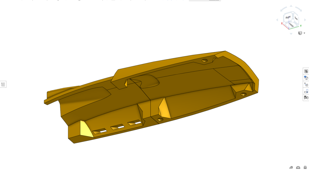
Turn the completed canopy over and apply a very small drop of CA into each magnet recess.
Establish the correct polarity
Hold the magnet stack over one of the magnets already installed in the fuselage. Turn the stack until its end magnet repels the fuselage magnet.
Keep this orientation. The face that repels the fuselage magnet is the face that should be pushed down into the canopy recess. Press the magnet into the CA, hold it down with a fingernail, and slide the remaining stack sideways.
The repelling face is now buried in the canopy, leaving the opposite pole exposed toward the fuselage. The installed magnets will therefore attract each other.
Install the canopy side section
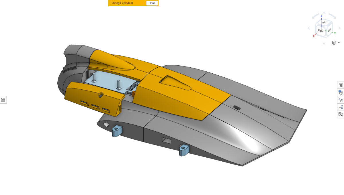
Dry-fit both the canopy side section and removable canopy before using glue. Clean away any support material that prevents the parts sitting naturally together. Extensive sanding should not normally be required.
Glue the canopy side section
Apply a small amount of CA to the bottom surface of the canopy side section and to its forward-facing surface where it meets the fuselage.
Place the side section approximately into position, but do not press it firmly down or allow the CA to cure yet.
Install the removable canopy and allow its magnets to pull it into its normal position. The canopy will naturally push the side section into the correct final alignment. Hold the side section gently in place until the CA cures.
Install the battery Velcro
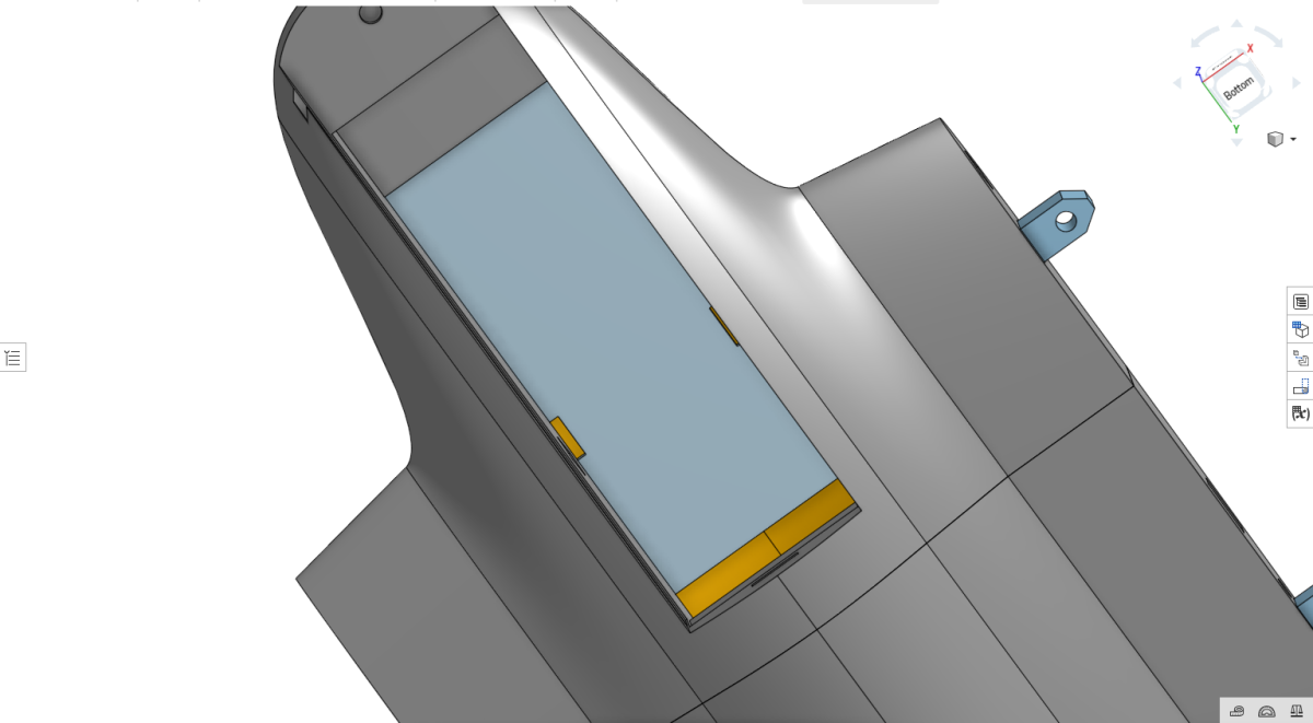
Apply Velcro tape to the lower face of the electronics bulkhead, facing into the battery bay.
Run it across approximately the rear three-quarters of the bulkhead, leaving the forward section clear.
The adhesive backing can be used to locate it, but adding a few small drops of CA underneath helps prevent the Velcro lifting from the printed surface over time.
Attach the inner wings
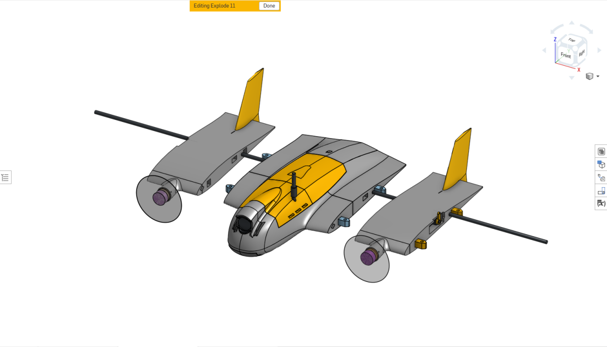
The inner wings must be fitted before the flight controller and main electronics package. Once the electronics are installed, there is much less room to pass the servo plugs through the fuselage.
Install the carbon-fibre spar
Slide the carbon-fibre spar, cut to the specified length, through the fuselage centre section.
Route the wiring
For each inner wing, pass the servo connector and cable through its wire channel and into the fuselage. Route the motor wires through their channel and into the centre section as well.
The electronics bulkhead has a notch on each side which allows the motor wires to pass upward from the battery bay into the electronics bay. Tweezers make it much easier to lift the motor wires through these openings.
Seat the inner wings
Slide each inner wing over the carbon spar and bring it carefully toward the fuselage while guiding the wiring. The wing should mate cleanly and flush against the fuselage.
Insert the M3 nylon wing bolts and check that they engage correctly with the previously installed wing-lock tabs. Repeat for the opposite wing.
Install and set up the electronics package
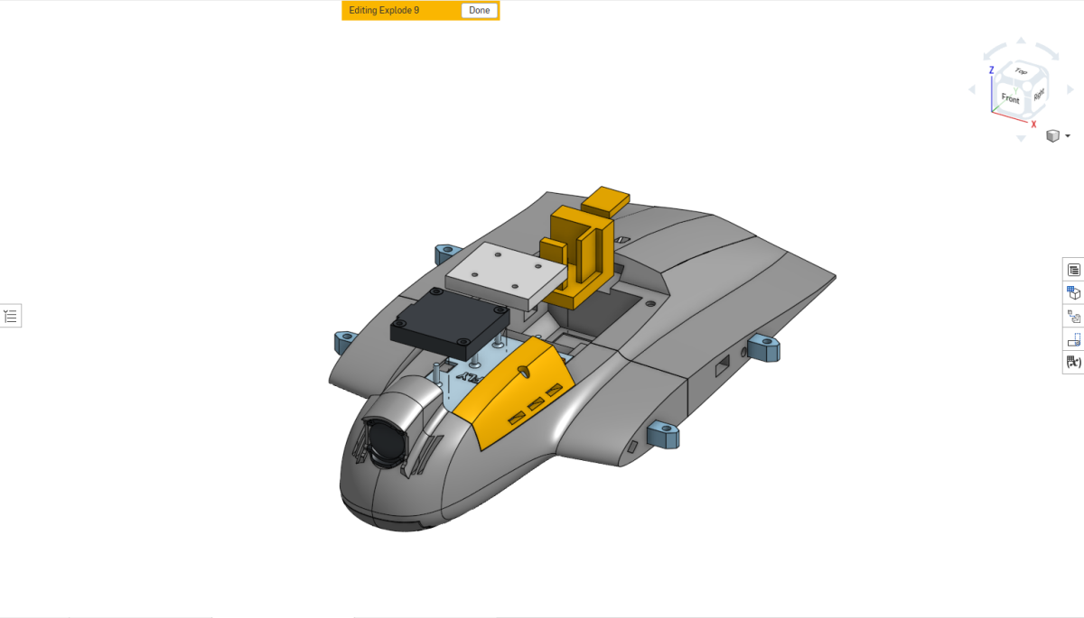
Install the FPV system
Slide the DJI O4 camera into the forward camera mount and install the VTX onto the mounting pins on the electronics bulkhead.
For the DJI O4 Wide and O4 Lite installations, orient the VTX so that its USB port faces pilot's right. This keeps the USB connection accessible with the canopy installed.
Install the ESC
Place the ESC onto its mounting position. Keep the motor wires only as long as necessary while still leaving sensible routing and a small amount of strain relief.
Install the flight controller
The reference aircraft shown uses the FlyingRC F4 Wing flight controller. Bond its supplied mounting base into the fuselage using CA, then use the supplied screws to retain the flight controller itself. This allows the FC to be removed later without disturbing the bonded mount.
Additional mounting solutions are being developed for compact fixed-wing boards including the SpeedyBee F405 Wing Mini and Matek F405-WMO.
Connect the motors
- Pilot's left motor → ESC motor channel 1
- Pilot's right motor → ESC motor channel 2
Keep the solder joints compact and route the wires without excessive tension.
Install the ELRS receiver
Feed the ELRS antenna through the dedicated channel in the rear fuselage. Connect it to the receiver and slide the receiver into the provided rear recess. The receiver can be retained with a small amount of hot glue or a small piece of Velcro.
The current space accommodates compact RadioMaster RP1/RP2-class ELRS receivers.
Set the servo horn positions
Once the electronics package has been installed and tested, complete the initial flight-controller setup and calibration.
- Remove the propellers.
- Place the aircraft physically level.
- Power the flight controller and receiver normally.
- Centre the transmitter sticks.
- Make sure no control input is being applied.
- Confirm that the FC correctly reports the aircraft as level.
The VTX does not need to be powered for this operation if your installation allows it to be disconnected.
With the servos powered at their commanded neutral positions, install each servo horn so that it is vertical, then install and tighten the retaining screw.
Attach the outer wing sections
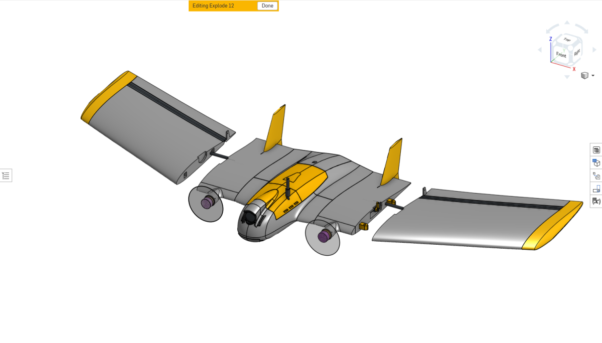
No glue is used in this step. The outer wings remain removable.
Check the spar
Make sure the carbon-fibre spar passes through the complete centre assembly without binding. It does not need to slide completely freely, but you should be able to reposition it without excessive force.
Install the outer wings
Slide each completed outer wing section onto the spar until the inner and outer wing sections meet cleanly and the wing-lock tabs align with the mounting holes.
Install the nylon wing bolts
Turn the aircraft over and install the M3 × 10 mm nylon bolts through the outer wing and into the PETG wing-lock tabs.
With the standard printed PETG threads, the nylon bolts may become snug and then continue turning rather than reaching a conventional hard stop.
Check elevon clearance
Move both elevons through their full range. If there is any rubbing, clicking, or binding, carefully remove a small amount of material from the elevon end or adjacent printed surface. Small amounts of elephant's foot can sometimes be enough to cause contact here.
Install the elevon linkages and set reflex
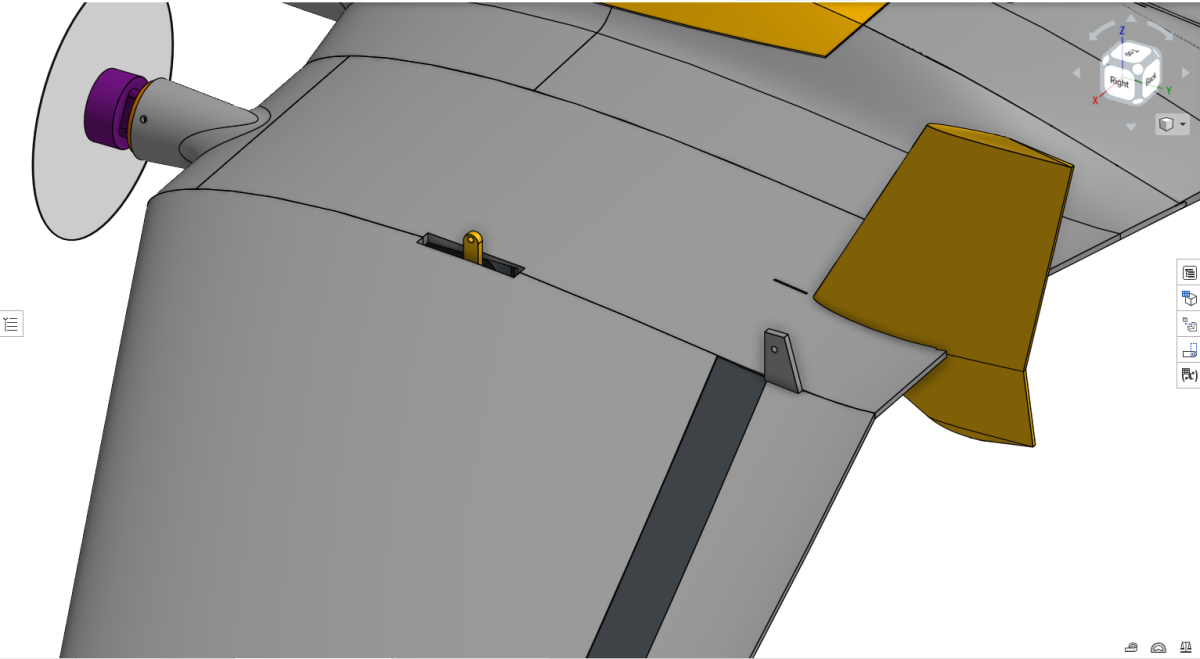
Install the pushrods
The metal servo pushrods should be approximately 55 mm long. Orient the kink so the linkage runs as straight as possible between the servo horn and elevon horn.
Make sure the adjustment screw faces outward so there is enough room to reach it with a screwdriver during adjustment.
Power the aircraft before setting reflex
The final mechanical neutral should be set with the servos powered.
- Remove the propellers.
- Place the aircraft level.
- Connect the battery.
- Power the flight controller and receiver.
- Centre the transmitter sticks.
- Make sure no control input is being applied.
Set the initial elevon reflex
Adjust the pushrod length so that each elevon sits with a small amount of upward reflex. Use the root of the elevon, where it meets the inner wing, as the reference.
Gently raise the elevon until its lower surface aligns with the upper surface of the adjacent inner wing section. This corresponds to approximately 1.2 mm of upward reflex at the trailing edge.
Match both sides
Repeat the adjustment on the opposite wing and make both sides as symmetrical as reasonably possible.
There will always be a small amount of mechanical play in the linkage, servo horn, and servo gearbox. Do not chase tiny differences caused by this slop. Concentrate on a consistent, symmetrical starting point with completely free control movement.
Wire.
Connect the power system, motors, flight controller, servos, receiver and video system. The exact power arrangement depends on whether your flight controller includes a suitable integrated BEC.
Understand the system first.
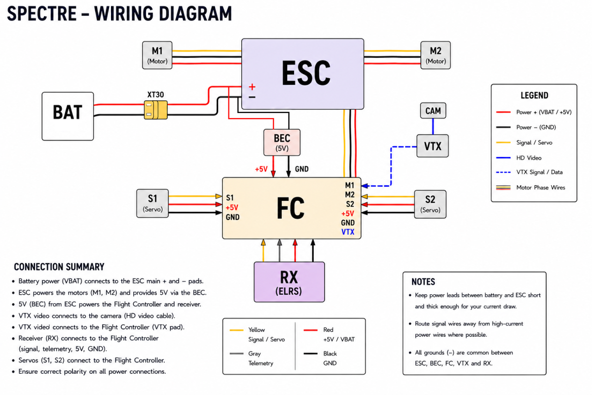
The diagram above shows the reference Spectre wiring arrangement using an external 5 V BEC. The battery connects to the ESC, the BEC takes battery voltage from those same ESC power pads, and the BEC provides regulated 5 V and ground to the flight controller.
From there, the flight controller provides the control connections for the motors, servos, receiver and video system.
BEC and flight-controller power
A BEC is a voltage regulator. The aircraft battery voltage is not the voltage used by the flight controller electronics, so the BEC provides the lower regulated supply they need. In the reference Spectre installation, this is 5 V.
Integrated or external BEC
If your flight controller has a suitable integrated BEC, a separate external BEC may not be required. Follow the power-input requirements for that board.
If your flight controller does not provide the required regulation, use an external 5 V BEC as shown in the wiring diagram.
External BEC input
The external BEC takes its input from the same positive and negative ESC pads used by the battery connection. Both the battery leads and the BEC input leads meet at the ESC main power pads.
The BEC then converts battery voltage to regulated 5 V.
BEC output
The BEC output consists of +5 V and ground. For the reference installation, these two wires can be terminated in a standard RC / servo-style connector and plugged into an unused flight-controller servo output. It is effectively a servo connector without the signal wire.
Supplying both 5 V and ground also establishes the common ground shared by the flight controller, ESC and battery system.
Set the wire lengths in the aircraft
Before cutting the battery, BEC or motor wiring to final length, place the electronics into their actual positions in the fuselage and check the routing with the canopy fitted.
This makes it much easier to establish the correct wire length and natural bend or twist before soldering. Leave enough length for comfortable assembly and servicing without carrying unnecessary excess wire inside the aircraft.
Pay particular attention to the battery lead. The battery should plug in comfortably without the connector or wiring pressing against the canopy.
Connect the main power system
Solder the battery positive and negative leads directly to the ESC main battery pads. The reference installation uses an XT30 battery connector.
If an external BEC is being used, solder its positive and negative input wires to the same ESC battery pads. This is the battery-voltage input for the BEC.
Keep the high-current battery wiring reasonably short and route it so the connector can be reached easily when installing or removing the battery.
Motor phase wires and rotation
Each motor has three phase wires which are soldered directly to the ESC.
- Pilot's left motor → Motor 1
- Pilot's right motor → Motor 2
The final motor direction is important. Both propellers should rotate outwards: the advancing blade should move toward the corresponding wingtip.
Swapping any two phase wires will reverse a brushless motor, but there is normally no need to resolder the motor wiring simply to change direction. Motor direction can be changed through the ESC / BLHeli configuration software and will be covered in the CONFIGURE section.
Connect the ESC to the flight controller
The flight controller needs to send an independent control signal to each motor channel, so there are two motor signal connections between the flight controller and the ESC: M1 signal and M2 signal.
On the reference Flywoo ESC, the ESC control electronics also require 5 V and ground. The reference wiring therefore uses one standard three-pin RC connector for Motor 1 carrying 5 V, ground and M1 signal.
Motor 2 then uses a second connector with a single wire carrying the M2 signal.
This gives both motor channels independent control while keeping the ESC connection compact and easy to disconnect.
Connect S1 and S2
The two elevon servos use their standard three-wire connectors and do not need to be modified.
- Left servo → S1
- Right servo → S2
Each normal servo connection carries signal, 5 V and ground.
Connect the ELRS receiver
The ELRS receiver connects directly to the flight controller.
On the reference FlyingRC F4 Mini, the receiver plugs into the UART connection on the top of the board.
The receiver uses four connections:
- 5 V
- Ground
- Signal
- Telemetry
Route the receiver antenna through the dedicated rear-fuselage channel and make sure neither the receiver nor its antenna wiring is trapped when the electronics and canopy are installed.
Connect the VTX and camera
The camera connects to the VTX using its normal video connection.
The VTX then connects to the flight controller using the appropriate VTX signal/data connection for the installed video system. The reference diagram shows this as the dashed blue VTX connection.
Keep the routing tidy and preserve access to the VTX USB port where applicable.
Before first power-up.
Once the electronics are assembled and soldered, work through the installation once before connecting the battery.
- Battery connector polarity matches the ESC battery pads.
- External BEC input is connected to the same ESC battery + and − pads as the battery.
- BEC output provides the correct regulated voltage to the flight controller.
- ESC and flight controller share a common ground.
- Pilot's left motor is Motor 1 and pilot's right motor is Motor 2.
- M1 and M2 signal connections are correctly assigned.
- Left servo is connected to S1 and right servo to S2.
- ELRS receiver power, ground, signal and telemetry connections are correct.
- Battery and motor wiring is not trapped or under unnecessary tension.
- The battery connector fits comfortably beneath the canopy.
- Propellers are removed for the first electrical and motor tests.
Built to come apart again.
The reference installation is arranged so that most of the central electronics can be disconnected using plugs rather than requiring extensive desoldering.
Once assembled, the principal soldered connections between the removable central electronics package and the wing-mounted hardware are the six motor phase wires — three per motor.
If the electronics package needs to be removed or replaced, the connectors can be unplugged and those six motor wires desoldered, allowing the central electronics to be taken out without dismantling the complete aircraft.
Configure.
Install INAV, load the supplied Spectre reference configuration, calibrate the flight controller and verify every output before fitting the propellers.
Start from the WUDFLY setup.
The Spectre download package includes a CLI configuration file. The CLI is a set of INAV commands containing the reference configuration used on the WUDFLY aircraft.
If you are using the same reference hardware, loading this file gives you the same starting configuration used on the reference Spectre and avoids having to recreate the complete setup manually.
The CLI is still a starting point for your aircraft. Board calibration, motor direction, servo direction, receiver operation and the other basic pre-flight checks must still be completed and verified on the finished model.
Install INAV Configurator

Start by installing INAV Configurator on your computer. It is the official cross-platform configuration application for INAV and is available for Windows, macOS and Linux.
Download it from the official INAV Configurator release page: Official INAV Configurator download .
The current official INAV documentation is also available here: Official INAV documentation .
If INAV is not already on the board
The reference Spectre uses the FlyingRC F4 Wing. If your board arrives running another firmware such as ArduPilot, INAV must be flashed before the Spectre CLI can be loaded.
The standard INAV flashing workflow is: connect the flight controller by USB, open Firmware Flasher, select the correct board/target and firmware, then flash the board. INAV's own installation guide recommends using Full Chip Erase when INAV is being flashed to a board for the first time.
Board-specific flashing details can vary, so check the documentation supplied with your flight controller before flashing if the target or bootloader procedure is unclear.
Load the supplied CLI
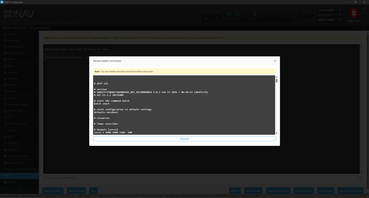
Once the flight controller is running INAV and connects normally to Configurator, locate the supplied Spectre CLI file in your download package.
Open the CLI section in INAV Configurator, choose Load from File, select the supplied Spectre configuration and load it into the CLI window.
Check that the file has loaded, then click Execute to send the configuration commands to the flight controller.
Allow the board to complete the process and reconnect if required.
Calibrate the flight controller
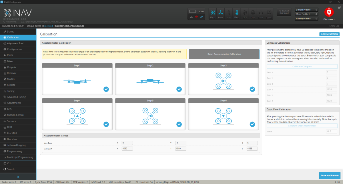
Loading the supplied CLI does not replace the normal INAV board calibration. The accelerometer calibration belongs to your individual flight controller and must be completed after the board is installed in the aircraft.
Open the Calibration page in INAV Configurator and work through the accelerometer routine shown above. Place the aircraft in each orientation requested by INAV and allow each position to register before moving to the next one.
Take your time with this step. The aircraft should be held steadily on each face so INAV can establish the board axes accurately.
When the calibration is complete, return the aircraft to its normal flying attitude on a level surface. The aircraft shown in INAV should agree with the real model: when Spectre is level, INAV should also report it as level.
Enable the outputs and set the ESC protocol
After the CLI is loaded and the board is calibrated, check the INAV output settings before attempting to run the motors.
Check the INAV output configuration and make sure the required motor and servo outputs are enabled for the aircraft.
Set the ESC protocol to DShot300.
This is also important if you need to use ESC Configurator passthrough to change motor direction. Without a compatible digital ESC protocol selected, the ESC configurator connection may not be available.
Check motor direction
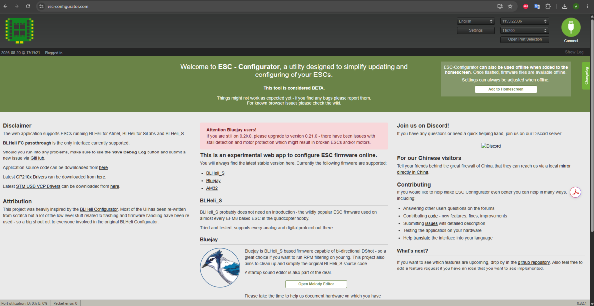
With the propellers removed, connect to the ESC configuration tool and check both motors.
The reference setup uses DShot300. With the digital ESC protocol configured correctly, the flight controller can be used to access the ESCs for configuration.
Spectre uses outward motor rotation. Viewed from the pilot's position, the propellers rotate away from the centreline, so the advancing blade travels toward the corresponding wingtip.
- Motor 1 → pilot's left motor
- Motor 2 → pilot's right motor
- Both motors → outward rotation
If either motor turns the wrong way, reverse that motor in ESC Configurator. Swapping any two motor phase wires also reverses a brushless motor, but software reversal is much easier once the aircraft is assembled.
Save the ESC setting, reconnect if required, and test both motors again at low output before continuing.
Before the propellers go on.
The aircraft should now be configured, powered and responding correctly without propellers fitted.
- INAV is installed and the flight controller connects normally.
- The supplied Spectre CLI has been loaded and executed.
- The accelerometer calibration has been completed.
- The aircraft is physically level when INAV reports level.
- The required PWM outputs are enabled.
- The ESC protocol is set to DShot300.
- Motor 1 is the pilot's left motor and Motor 2 is the pilot's right motor.
- Both motors rotate outward.
- Left servo is S1 and right servo is S2.
- Servo movement and control directions have been checked.
- The ELRS receiver is connected and responding.
- Flight modes, failsafe and launch settings have been reviewed.