
VENOM Build Guide
Print, assemble and prepare the 600 mm V-tail FPV aircraft.
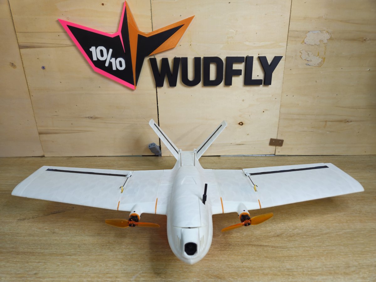
This guide follows VENOM from printed parts through fuselage, modular wing and V-tail assembly, electronics installation and flight setup. PRINT 00–16 and BUILD 01–24 are documented from the current reference build. Wiring and configuration will be completed after verification.
Four phases.
The VENOM manual uses the same four chapters as SPECTRE: PRINT, BUILD, WIRE and CONFIGURE. The print and assembly procedures are documented for this airframe; wiring and setup are adapted to the four-servo Matek reference, with remaining pinout and CLI details called out where not yet confirmed.
Build overview.
Reference configuration: Matek F405-Wing WMO, twin VCI Spark 1103 motors, DJI O4 Wide, and a 2S Explorer 1000 mAh LiHV battery. Tables below reproduce the supplied revision-01 BOM values.
Complete reference aircraft BOM · 249.4 g
| Part | Qty | Description / Specification | Unit (g) | Total (g) |
|---|---|---|---|---|
| BAT | 1 | Explorer 1000mAh LiHV 2S 80C Battery | 45.3 | 45.3 |
| FC | 1 | MATEK F405 WING WMO + FC Cable | 11.4 | 11.4 |
| ESC | 1 | HAKRC 4-in-1 25A ESC | 6.0 | 6.0 |
| MOT | 2 | VCI Spark 1103 — 11000KV Motor | 4.4 | 8.8 |
| PROP | 2 | Gemfan 3020 | 1.0 | 1.9 |
| SERVO | 4 | DSPOWER 3.7G S002M JR2.54 | 4.7 | 18.8 |
| RX | 1 | RadioMaster RP1 ELRS Receiver | 1.7 | 1.7 |
| FPV | 1 | DJI O4 Wide Camera | 8.3 | 8.3 |
| FPV | 1 | DJI O4 VTX | 5.2 | 5.2 |
| FPV | 1 | VTX Cable | 1.2 | 1.2 |
| CAP | 1 | 35V 2200µF Capacitor | 0.8 | 0.8 |
| FRAME | 1 | Complete Airframe Assembly (Section 02) | 140.0 | 140.0 |
| REFERENCE AIRCRAFT TOTAL | 249.4 | |||
Detailed airframe and hardware inventory · 140.2 g
| Part | Qty | Description | Unit (g) | Total (g) |
|---|---|---|---|---|
| LW-PLA | 1 | Fuselage Front | 19.8 | 19.8 |
| LW-PLA | 1 | Fuselage Rear | 14.8 | 14.8 |
| LW-PLA | 1 | Camera Mount | 1.4 | 1.4 |
| LW-PLA | 1 | Battery Access | 2.5 | 2.5 |
| LW-PLA | 1 | Canopy Front | 1.6 | 1.6 |
| LW-PLA | 1 | Canopy Rear | 4.8 | 4.8 |
| LW-PLA | 1 | Canopy Side | 0.7 | 0.7 |
| LW-PLA | 2 | Inner Wing | 7.5 | 15.1 |
| LW-PLA | 2 | Inner Wing Leading Edge | 2.0 | 4.0 |
| LW-PLA | 2 | Outer Wing | 14.5 | 28.9 |
| LW-PLA | 2 | Wing Tip | 2.2 | 4.4 |
| LW-PLA | 2 | V-Tail | 3.2 | 6.4 |
| TPU | 2 | Ruddervator Hinges | 0.2 | 0.4 |
| TPU | 2 | Elevon Hinges | 0.2 | 0.4 |
| PETG | 1 | Fuselage Bulkhead | 3.3 | 3.3 |
| PETG | 2 | Inner Leading Edge Bracket | 0.2 | 0.3 |
| PETG | 2 | Outer Leading Edge Bracket | 0.3 | 0.6 |
| PETG | 10 | WingLoc | 0.3 | 2.7 |
| PETG | 2 | Motor Mount (inc. 4 × M2×5 Button Head Screws) | 1.1 | 2.3 |
| CLIP | 4 | Servo Horn Clips | 0.3 | 1.3 |
| CARBON | 2 | Carbon Rod — 2mm OD × 80mm | 0.4 | 0.7 |
| CARBON | 1 | Carbon Rod — 3/1.5mm × 520mm | 4.2 | 4.2 |
| LINKAGE | 2 | Elevon Control Rod and Clip — 53mm | 0.8 | 1.6 |
| LINKAGE | 2 | Ruddervator Control Rod — 139mm | 1.3 | 2.6 |
| SCREW | 8 | M3 Nylon Threaded Screws | 0.0 | 0.4 |
| SCREW | 16 | M1.4×5 Self-Tapping Screws — Brackets | 0.1 | 0.9 |
| SCREW | 8 | M1.4×5 Self-Tapping Screws — Motor Mount | 0.0 | 0.4 |
| SCREW | 8 | M2×4 Button Head Screws — Motor | 0.2 | 1.6 |
| SCREW | 4 | M2×6 Button Head Screws — Propeller | 0.2 | 0.8 |
| SCREW | 4 | M1.7×6 Self-Tapping Screws — FC | 0.1 | 0.6 |
| SCREW | 8 | M1.7×6 Self-Tapping Screws — Servo | 0.1 | 1.1 |
| WIRE | 6 | 150mm AWG28 Motor Wire Extensions | 1.0 | 6.0 |
| WIRE | 2 | 60mm AWG18 FC to ESC | 0.8 | 1.5 |
| WIRE | 2 | 40mm AWG18 Battery to ESC, inc. XT30 | 1.1 | 2.1 |
| DETAILED AIRFRAME TOTAL | 140.2 | |||
Print.
Recommended print orientations, supports, Z-seam settings and material choices for PRINT 00–16. Follow the illustrated slicer screenshots; values not stated here should be taken from the supplied print profiles.
Parts, materials and build plates.
The complete VENOM printed-part set is shown below. Start here to identify the main structural parts, mirrored pieces and small hardware before preparing the individual print plates.
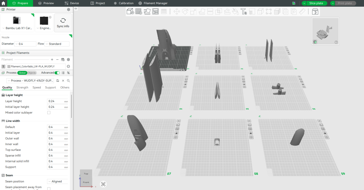
The primary airframe uses ColorFabb LW-PLA. Functional attachment components, wing locks, brackets and the electronics bulkhead are printed in PETG. Both the elevons and V-tail ruddervators use separate TPU hinges.
VENOM uses a modular wing structure, with removable wing assemblies, carbon reinforcement and replaceable attachment hardware. Check that the left and right pieces match before you start assembly.
Use the WUDFLY print profiles as the material baseline, then follow the aircraft-specific orientations, infill settings and support exclusions below.
Keep the build plates simple
Group components sensibly, prioritising clean parts and repeatable prints over packing every available space on the bed. LW-PLA can string during long travel moves, so smaller print jobs are often easier to clean and less costly to repeat after a failed print.
Functional PETG parts
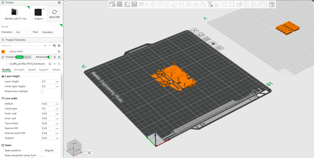
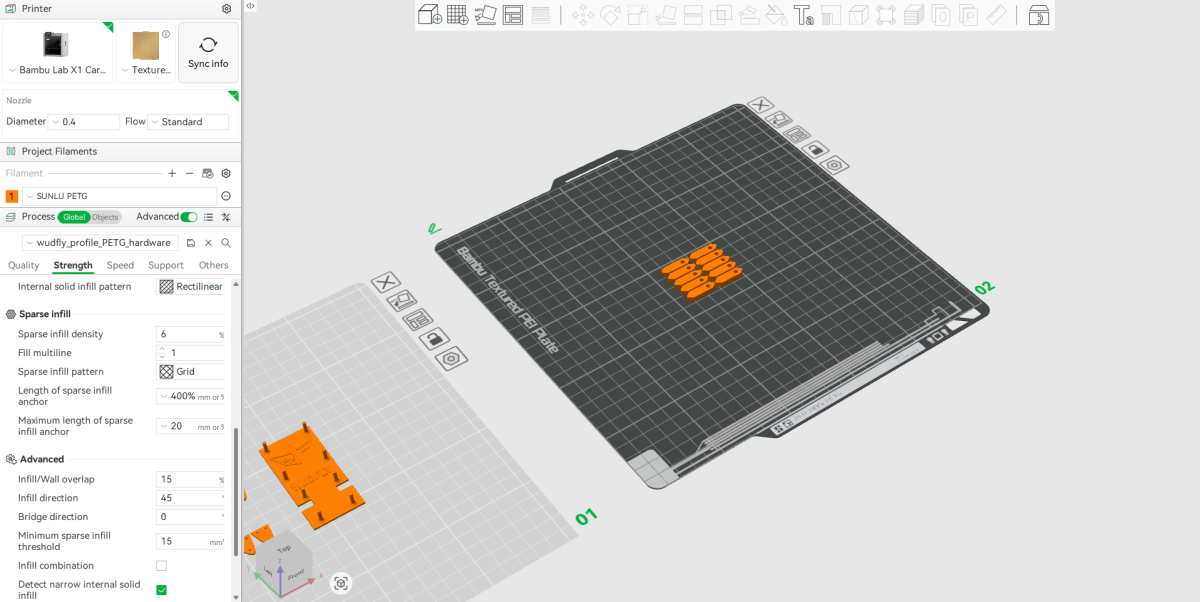
Print the smaller structural and attachment components in PETG. The reference PETG plates use approximately 6% grid infill; use the accompanying slicer settings for the remaining parameters.
Electronics bulkhead
The PETG bulkhead holds the flight electronics and faces the VTX/ESC installation. It needs enough stiffness to retain the equipment and tolerate repeated battery installation and removal.
Leading-edge brackets and canopy retaining C-clip
The PETG plate also includes the left and right inner and outer leading-edge attachment brackets and the canopy retaining clip. Identify the mirrored brackets before assembly and keep their screw holes clear.
WingLoc tabs
Use the second image for the WingLoc tabs. Dimensional accuracy, clean threads and correct mounting orientation matter more than heavy infill. Print a few extra tabs as spares; they are small and easy to keep with the aircraft.
Motor attachment hardware
The BOM lists the motor mounts as PETG components. Make sure you identify the corresponding files in the release pack and follow their supplied print profile; the separate PRINT 08 illustration shows the motor-mount-related build plate.
Fuselage Build Plate Orientation
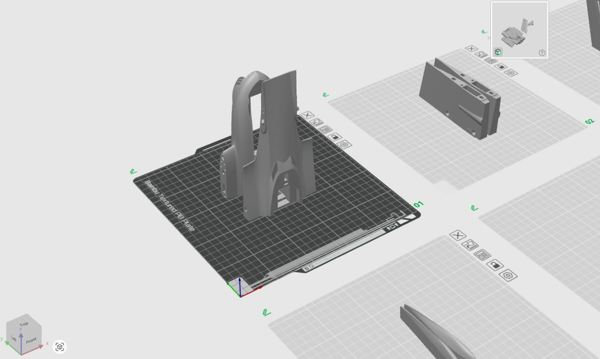
Position the front and rear fuselage sections close together on the build plate, with the top of each section facing outward.
This arrangement helps keep any stringing in accessible areas, making it easier to remove after printing rather than having it collect inside the fuselage.
Infill: 4% gyroid.
Rear Fuselage Supports
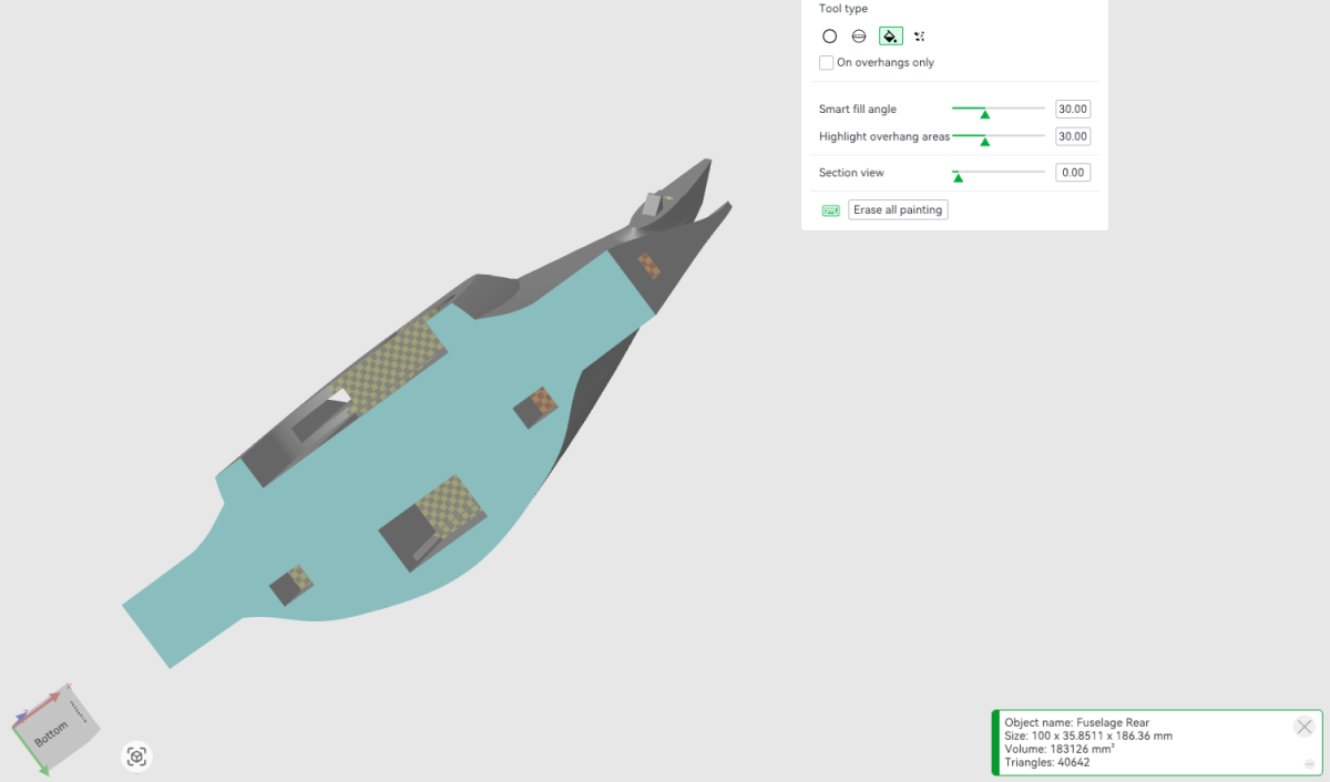
This image shows the underside of the rear fuselage section and identifies the areas where supports must be disabled.
Use support blockers or support painting to prevent supports from being generated in the indicated locations.
Use the highlighted exclusions in the image as the VENOM-specific support reference.
Infill: 4% gyroid.
Front Fuselage Supports
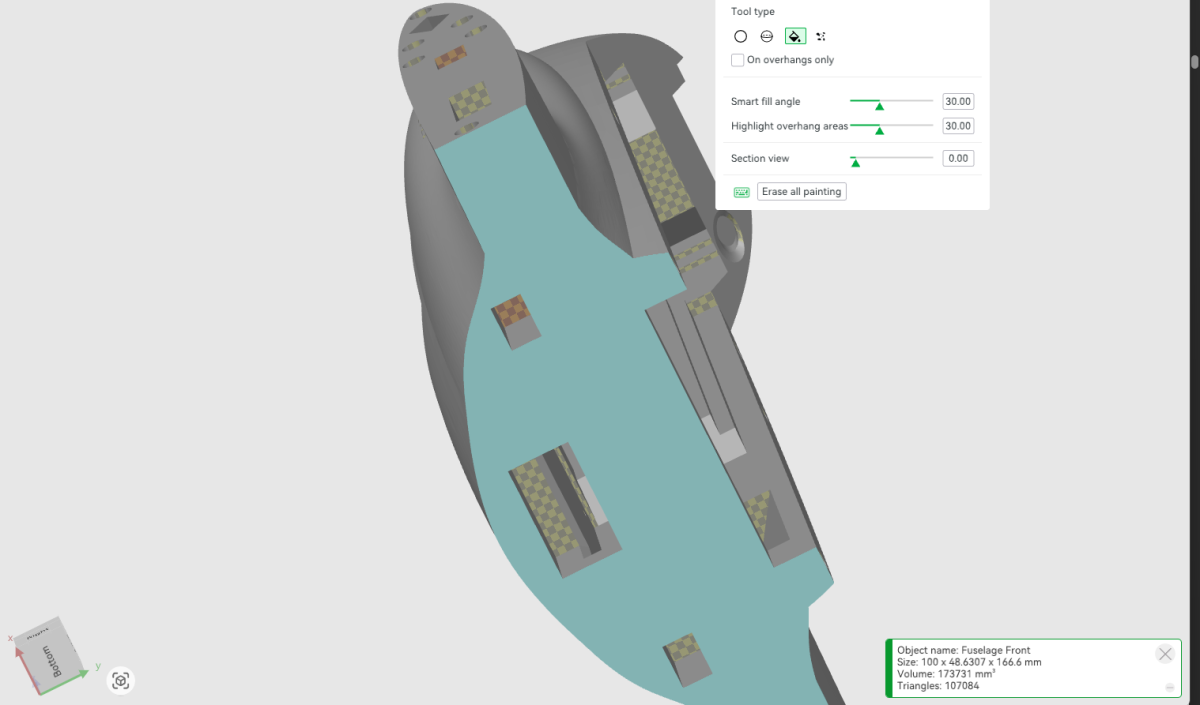
This image identifies the support exclusions required for the front fuselage section.
Follow the illustrated support placement and prevent supports from being generated in the indicated areas.
Infill: 4% gyroid.
Inner Wing Sections
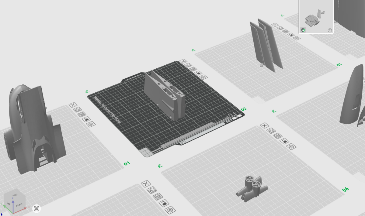
Position the inner wing sections on the build plate as shown in the image.
Infill: 3% gyroid.
V-Tail and Ruddervator Orientation
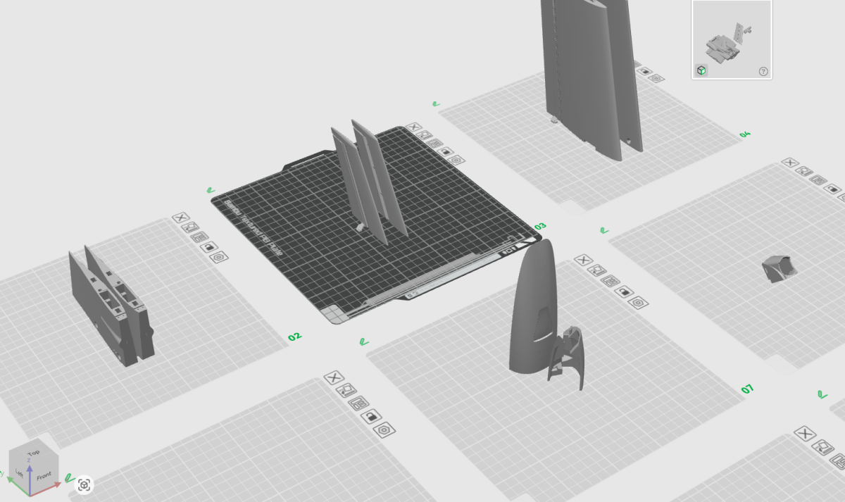
Each V-tail section and its ruddervator control surface are printed together as a single assembly. The control surfaces are subsequently connected using the separate TPU hinges.
Position the two assemblies with their control horns facing outward, away from each other.
Orient each assembly so that the flat underside of the control horn rests against the build plate.
Set the Z-seam to the rear of both parts.
Infill: 8% gyroid.
V-Tail Support Exclusions
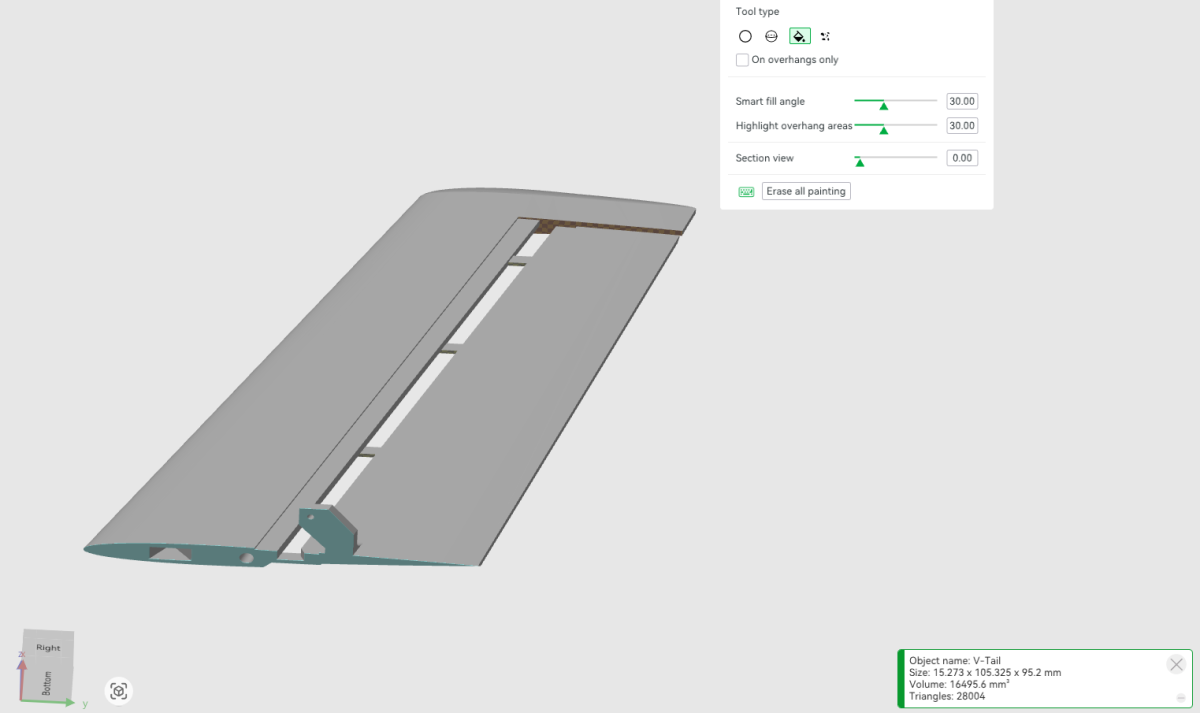
This image shows the underside of the V-tail, specifically the overhanging area near the top of the ruddervator where the control surface meets the fixed tail.
An overhang is present across the gap between these two sections.
Disable supports for this overhang using the indicated support exclusions.
Use the image as a reference for the precise exclusion areas.
Outer Wing Sections
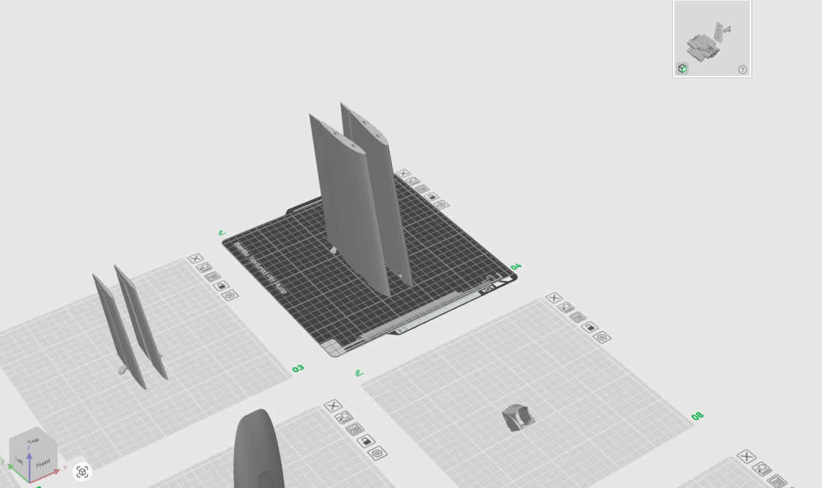
Position the outer wing sections with their control horns facing outward, following the same general orientation approach used for the V-tail assemblies.
This orientation helps ensure that the channels receiving the TPU elevon hinges are printed cleanly and accurately.
Set the Z-seam to the rear on both wing sections.
Infill: 3% gyroid.
Wingtips
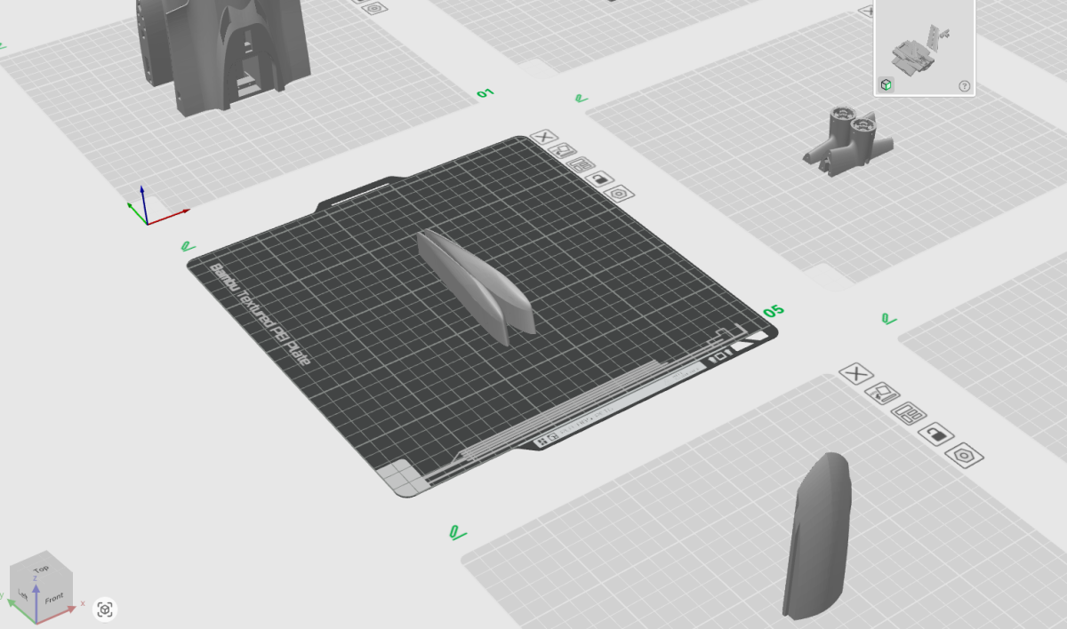
The wingtips are straightforward to print and do not require any special preparation.
Position them as illustrated.
Infill: 3% gyroid.
Motor-mount-area components
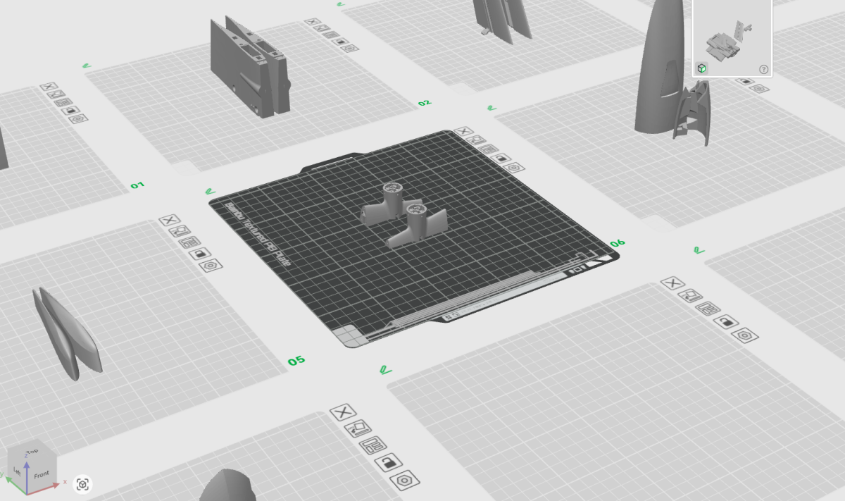
Arrange the motor-mount-area components as illustrated. The supplied PRINT 08 note calls for 8% gyroid infill with no unusual support requirements.
Several motor and leading-edge parts have similar names. Follow the specific STL and supplied slicer profile for each component. The PETG motor mounts specified in the BOM are also covered in the functional PETG section above.
Canopy Components
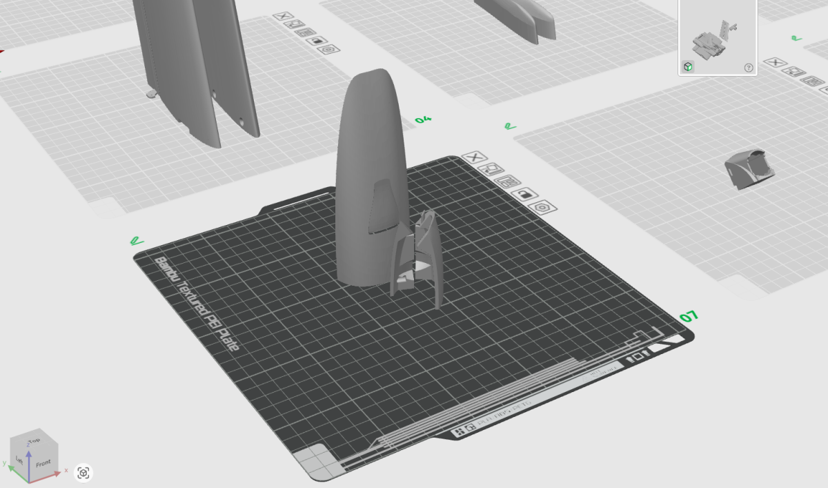
All canopy components can be printed together on the same build plate.
Position the components vertically as illustrated. No special preparation is necessary.
Infill: 3% gyroid.
DJI O4 Wide Camera Mount
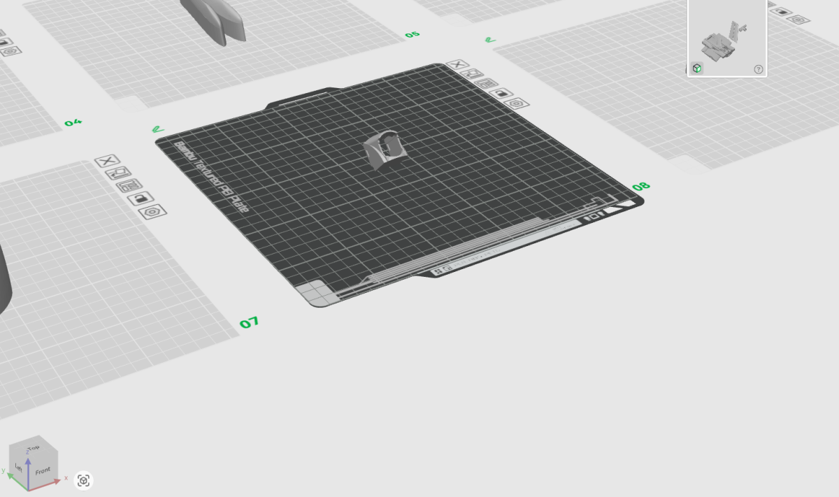
This component is the camera mount for the DJI O4 Wide Air Unit.
The mount needs to be rotated to an angle of 45° on the build plate before printing.
The following images show the rotation and support configuration.
Infill: 3% gyroid.
Camera Mount Rotation
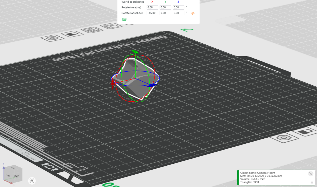
This image demonstrates the rotation tool in Bambu Studio.
Use the rotation tool to position the camera mount at 45°, as shown.
Camera Mount Supports
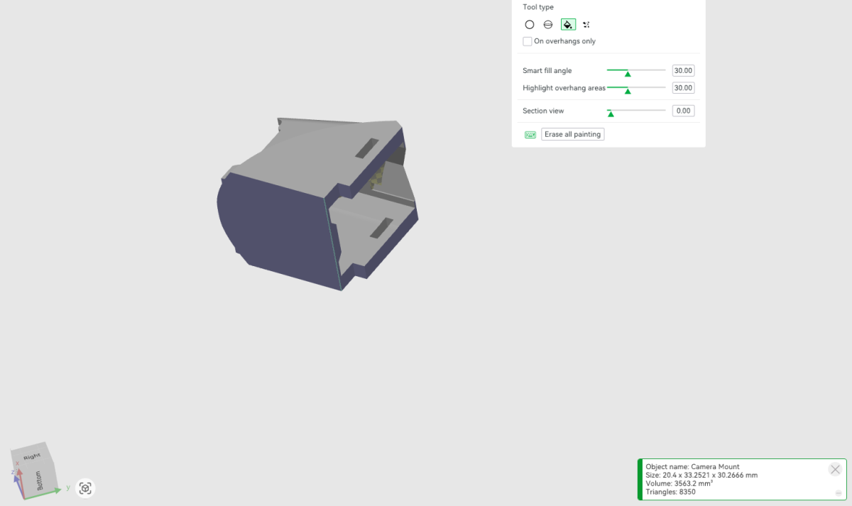
The underside of the camera mount is shown with the areas requiring supports painted in blue.
Apply support painting to the indicated underside surfaces.
Automatic support generation can then be used to generate the additional supports required for the internal and upper sections of the mount.
Infill: 3% gyroid.
Battery Tray / Battery Access
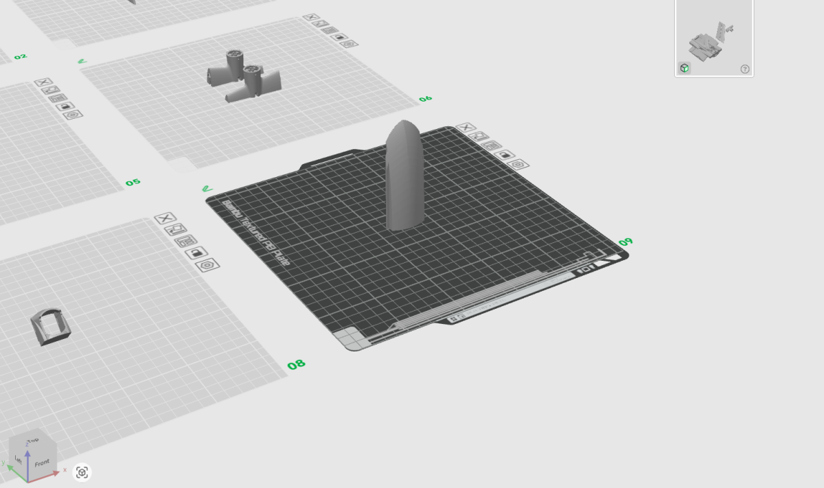
Print the battery tray and battery access components in the orientations shown.
No special preparation is required.
Infill: 3% gyroid.
TPU Control Surface Hinges
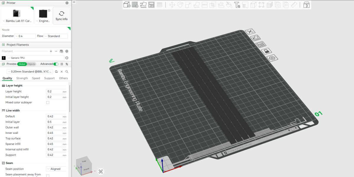
The TPU hinges are used for both the wing elevons and the V-tail ruddervators.
The image shows four hinges arranged on each build plate.
Since these small components require switching to TPU, it is more efficient to print several sets at once.
Keep the additional hinges stored as spares for future builds or repairs. This avoids having to change filament and reconfigure the printer every time a replacement hinge is needed.
Materials and infill.
These values are transcribed from the current VENOM print instructions; use the matching slicer screenshots and material profiles for all remaining parameters.
| Component | Material | Infill |
|---|---|---|
| Fuselage sections | LW-PLA | 4% gyroid |
| Inner wing sections | LW-PLA | 3% gyroid |
| Outer wing sections | LW-PLA | 3% gyroid |
| Wingtips | LW-PLA | 3% gyroid |
| V-tail / ruddervator assemblies | LW-PLA | 8% gyroid |
| Motor mounts | LW-PLA | 8% gyroid |
| Canopy components | LW-PLA | 3% gyroid |
| Camera mount | LW-PLA | 3% gyroid |
| Battery tray / access | LW-PLA | 3% gyroid |
| Structural hardware and brackets | PETG | ~6% grid |
| Wing lock tabs | PETG | ~6% grid |
| Control surface hinges | TPU | Refer to print profile |
Build.
Fuselage, V-tail, modular wing, motor and electronics installation. BUILD 01–24 and the additional BUILD 03.5 follow the numbered assembly artwork. Check the noted illustration revisions before final publication.
Joining the Fuselage Sections
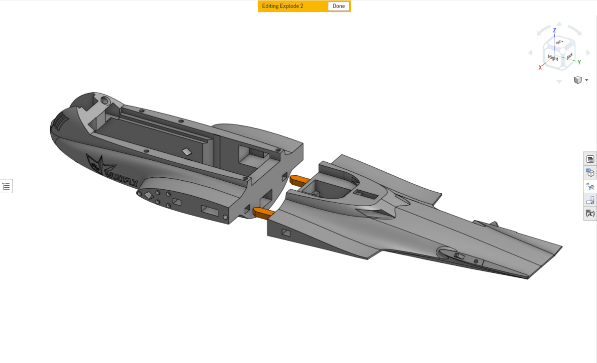
The front and rear fuselage sections are joined using the PETG wing lock tabs.
Start by dry-fitting the tabs into one fuselage section. Make sure they are fully seated at the bottom of their slots, then bring the two fuselage sections together to check the fit.
Once satisfied, apply superglue to both mating surfaces and join the sections.
The tabs can be installed in either fuselage section, although gluing them into one side first makes assembly easier.
Wing Root Lock Tabs
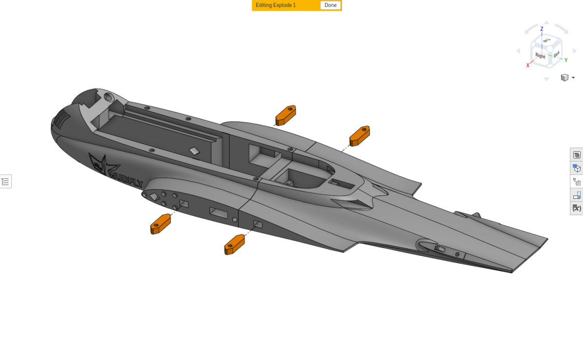
Install the wing lock tabs into the wing root attachment points.
Important: The holes in the tabs must face outward so that the wings can be secured from underneath the aircraft.
Dry-fit the tabs, check their orientation and glue them securely in position.
Fuselage Bulkhead and Magnets
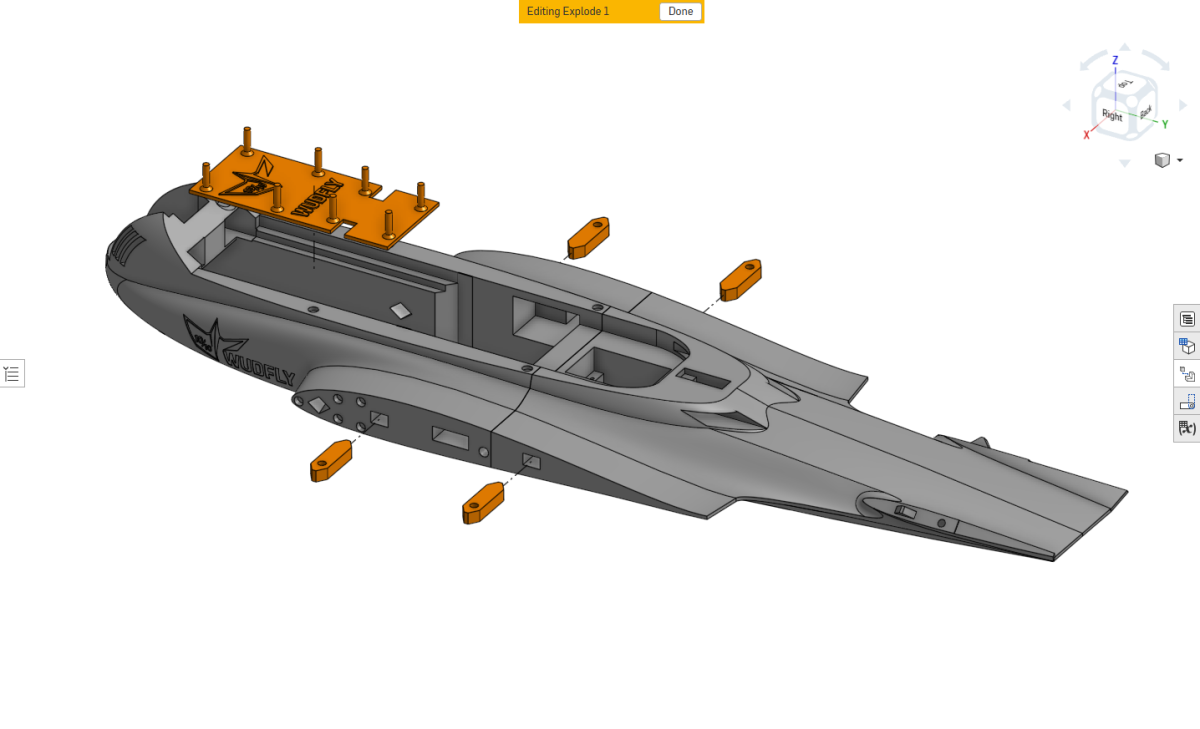
Install the PETG fuselage bulkhead into the front fuselage compartment using superglue.
Make sure the bulkhead is seated correctly before the adhesive sets.
Install the fuselage canopy retention magnets into their designated recesses, checking that their polarity matches the corresponding canopy magnets.
Battery Retention
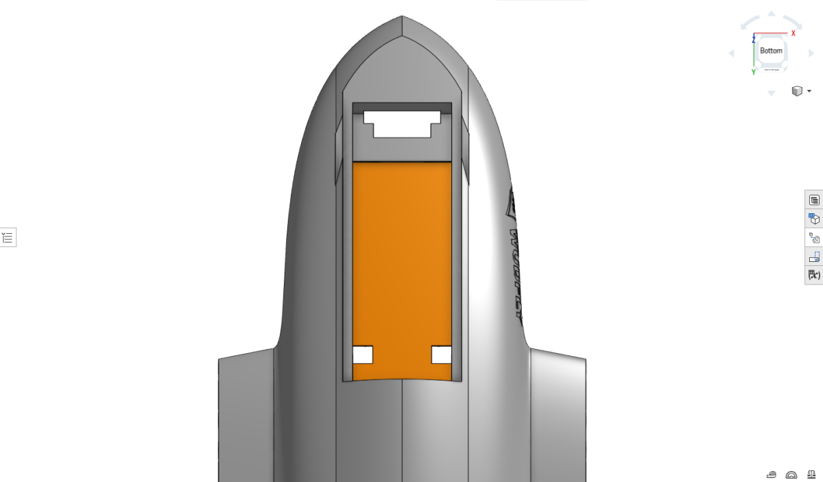
Apply the Velcro battery retention tape to the underside of the battery tray, as shown.
This provides the attachment point for securing the battery during flight.
V-Tail Carbon Rods
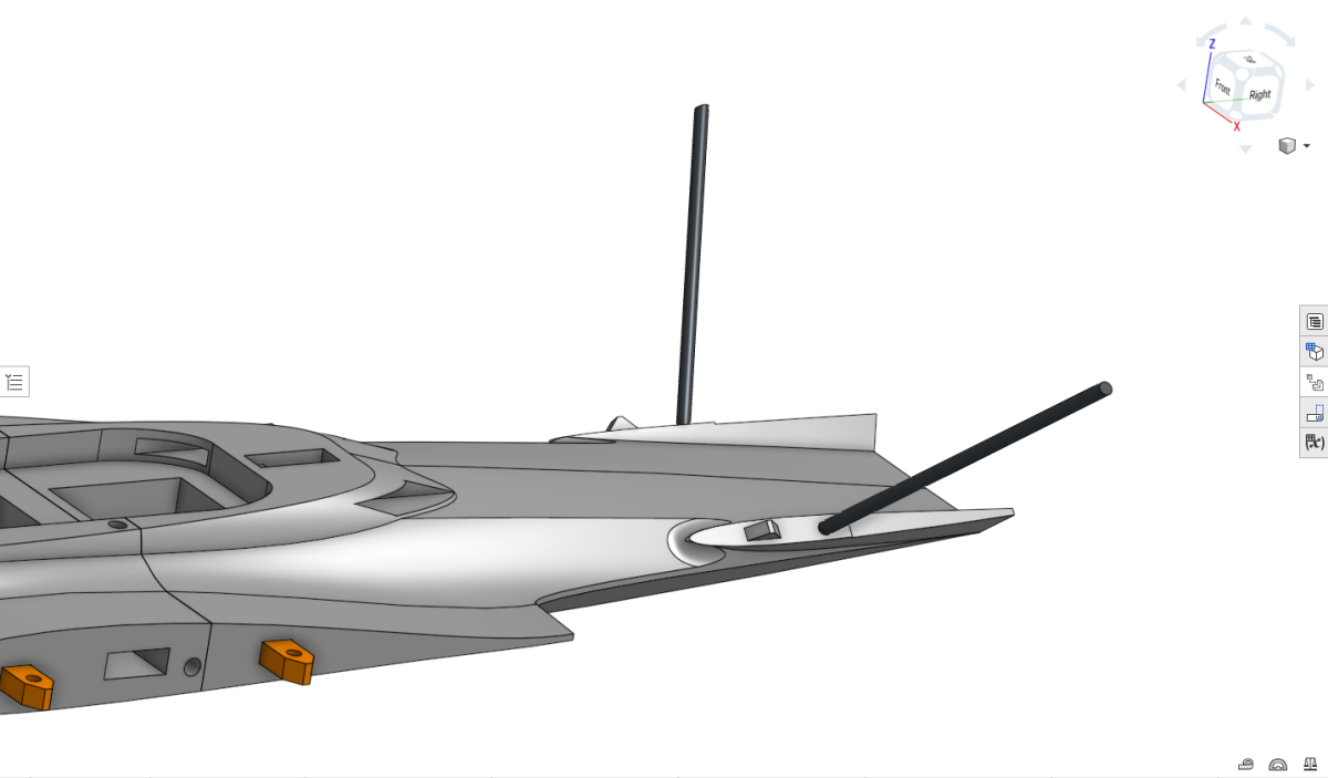
Install the carbon-fibre support rods into the rear fuselage tail mounting points.
Before gluing anything, dry-fit the rods together with the V-tail assemblies.
Check that:
- The rods reach the bottom of their mounting holes.
- The V-tail indexing keys engage correctly.
- The V-tail assemblies sit flush against the fuselage.
- The rods are not too long and do not prevent the assemblies from seating fully.
Cut or adjust the rods as necessary before final assembly.
The reference BOM lists two 2 mm OD × 80 mm carbon rods for the V-tail supports. Confirm the fitted lengths against the actual printed parts before gluing.
Ruddervator TPU Hinges
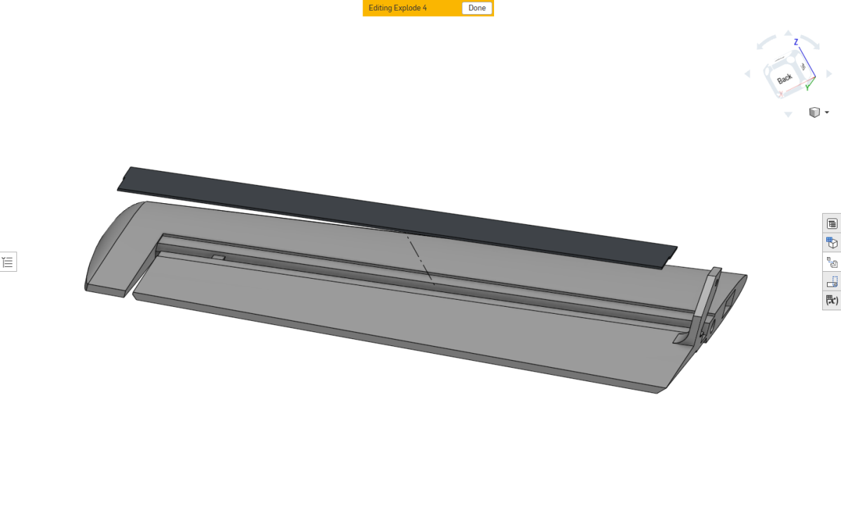
The ruddervator hinges are installed using the printed TPU hinge strips and superglue.
Start by positioning the hinge strip in its channel on the upper surface. Tack one end into place with superglue and allow it to bond.
Once secured, carefully lay the remaining hinge strip into the channel.
Apply superglue to both mating surfaces, ensuring the adhesive extends all the way to the edges of the hinge trench.
Use a damp sponge to press the TPU strip firmly and evenly into position while the adhesive sets.
Important: Make sure the full width of the hinge is bonded, particularly along the edges of the channel.
Allow the adhesive to cure before trimming the hinge to its final length.
The image shows the hinge already trimmed, but trimming should be performed after gluing.
Freeing the Ruddervators
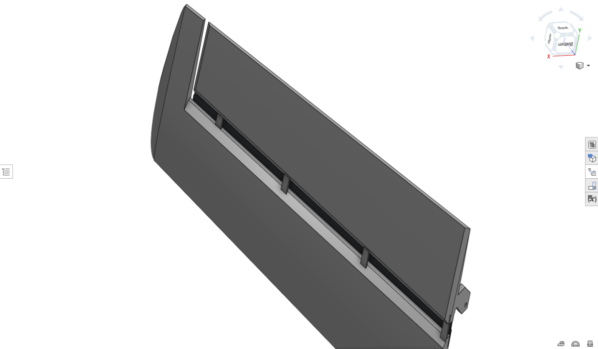
The ruddervators are printed together with their fixed V-tail sections and are initially connected by small printed tabs.
Once the TPU hinges have been installed and the adhesive has cured, these connecting tabs must be removed.
Use a thin razor blade to carefully cut the tabs from behind.
Take care not to cut or damage the TPU hinge.
After removing the tabs, check that the ruddervator moves freely.
Some excess printed material may need to be removed near the ruddervator tip, where it approaches the upper section of the fixed V-tail.
Check the full range of movement and remove any interference.
Installing the V-Tail Assemblies
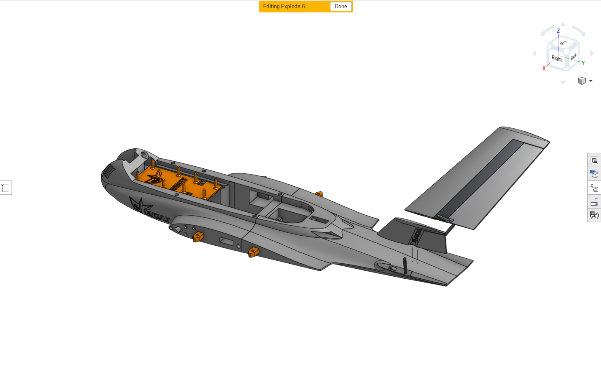
Slide the completed V-tail assemblies onto the carbon-fibre rods installed in the rear fuselage.
Alternatively, the rods can be installed into the V-tail assemblies first and then inserted into the fuselage.
Ensure the indexing keys engage correctly and the assemblies sit completely flush against their mounting surfaces.
Once satisfied with the fit, secure the assemblies using superglue.
Important: Avoid getting adhesive between the movable ruddervator and the fixed V-tail root. The control surfaces must remain completely free to move.
Ruddervator Servos and Pushrods
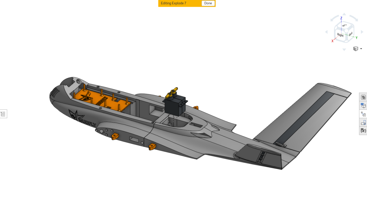
Install the two ruddervator servos side by side in the rear fuselage.
Pass the servo wires through their channels into the main fuselage electronics compartment before positioning the servos.
Seat the servos in their mounting points and secure them using the supplied servo screws.
Prepare the steel control pushrods for both ruddervators.
The reference BOM lists 139 mm ruddervator control rods. Confirm the steel rod diameter with the supplied part before cutting or bending the pushrods.
The control linkages will be connected later in the assembly.
Canopy Assembly
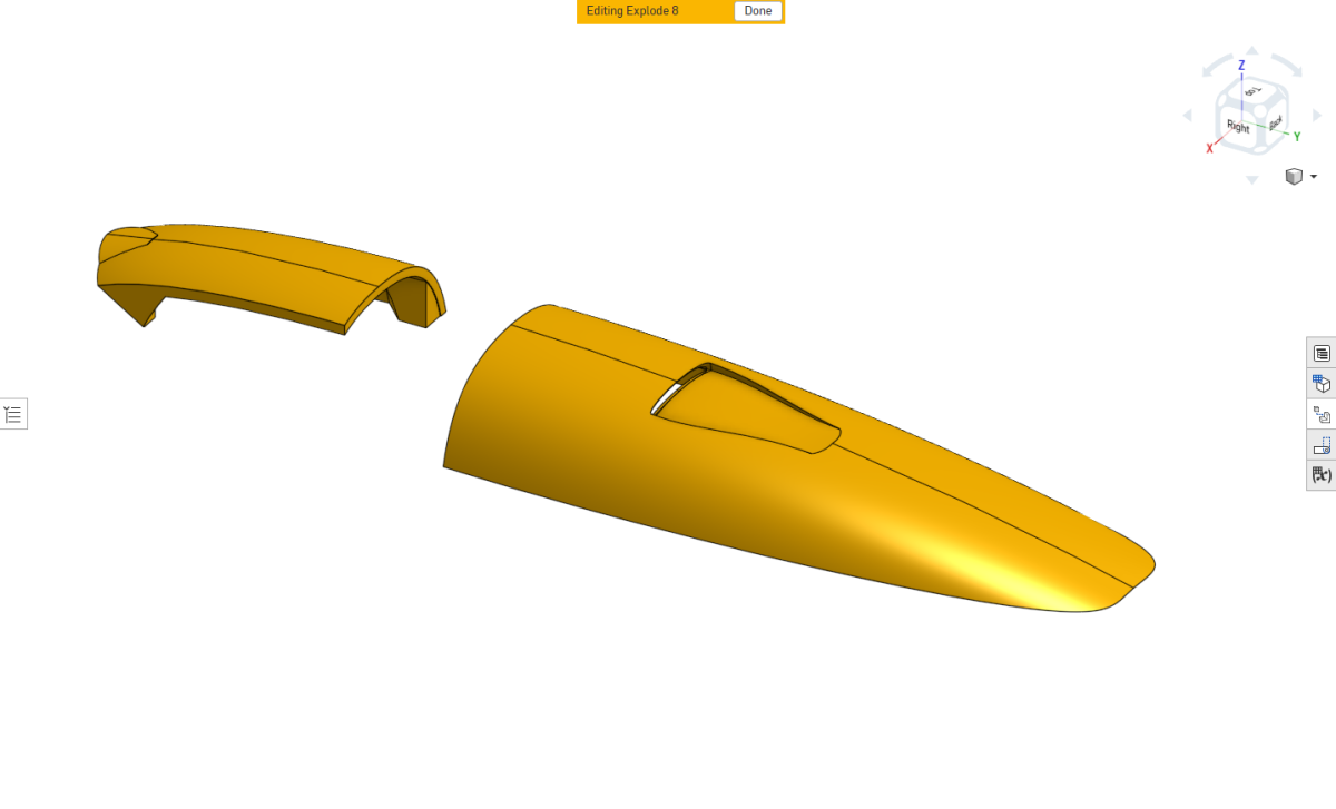
Join the front and rear canopy sections together using superglue.
Check the alignment and fit before gluing.
Canopy C-Clip and Magnets
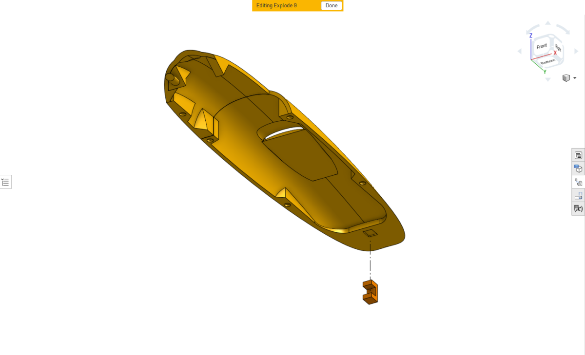
Install the PETG retaining C-clip into the assembled canopy using superglue.
Install all canopy retention magnets into their designated recesses.
Check the polarity against the corresponding fuselage magnets before applying adhesive.
Motor and Leading-Edge Assembly
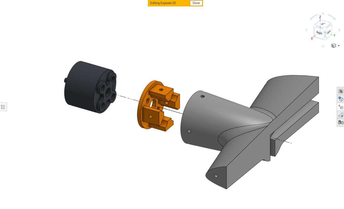
The motor mount is installed inside the removable wing leading-edge section.
Start by dry-fitting all components to ensure that the motor mount seats correctly inside the leading-edge assembly.
Attach the motor to its printed motor mount using the mounting screws supplied with the motor.
Make sure the motor is firmly secured.
Slide the assembled motor and mount into the wing leading-edge section.
Secure the mount using four M1.4 screws, approximately 4–5 mm in length. The reference BOM specifies M1.4 × 5 mm self-tapping screws for the motor-mount attachment.
Route the motor wires through the designated cable channel so that they can pass through the wing and into the fuselage.
Inner Wing Lock Tabs and Servos
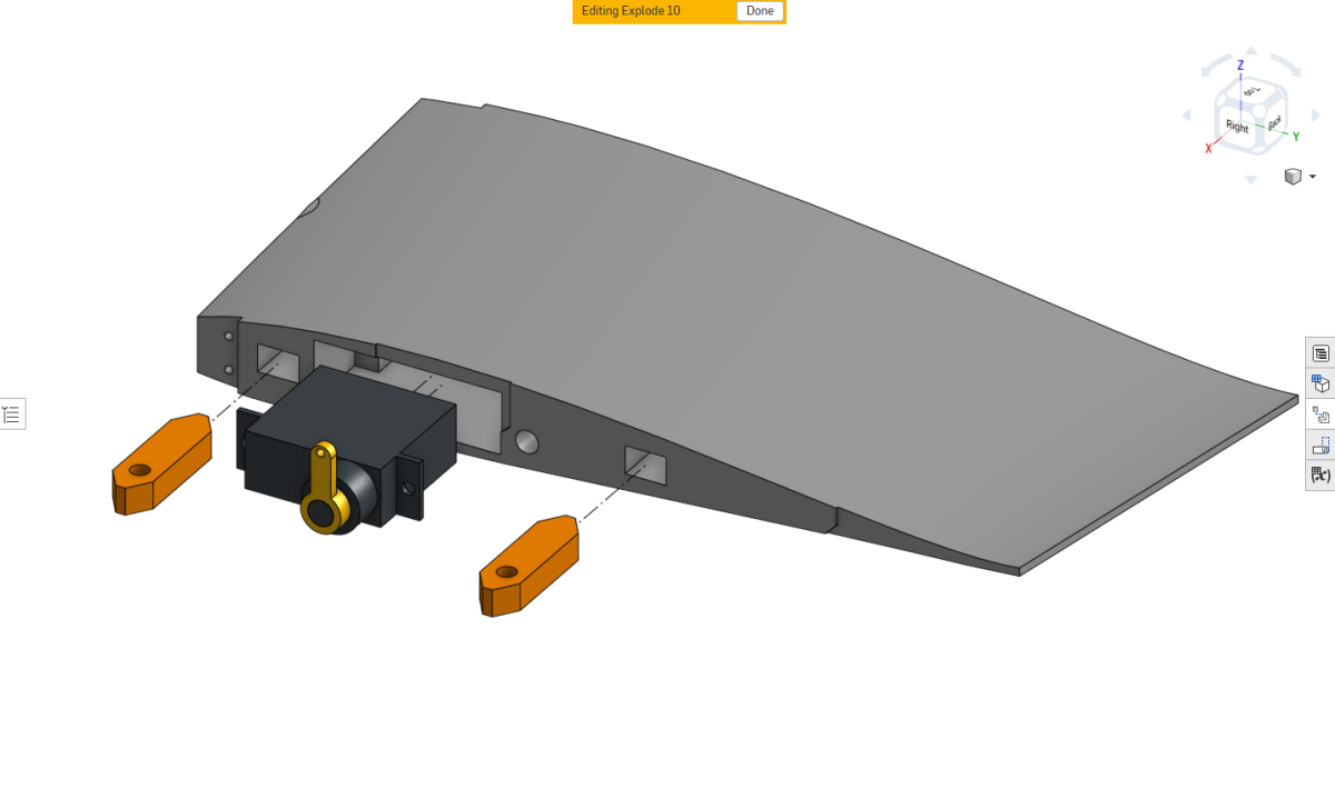
Install the wing lock tabs into the inner wing sections using the same dry-fitting and gluing procedure described previously.
Ensure the tabs are correctly oriented for the wing attachment hardware.
Install the wing servos into their designated mounting points.
The servos slide into place and are secured using the screws supplied with the servos.
Inner Wing and Leading-Edge Assembly
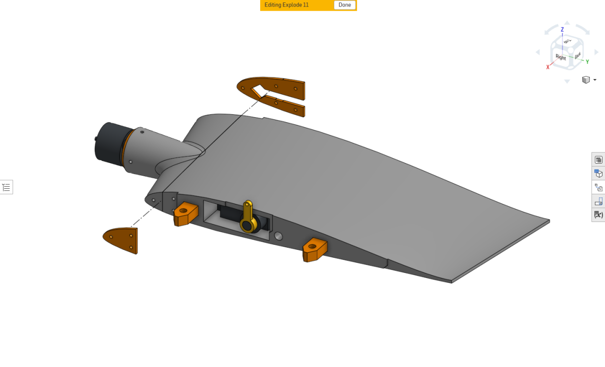
With BUILD 11 and BUILD 12 completed, you should now have the motor installed in its mount, the leading-edge section prepared, and the inner wing section fitted with its servo and attachment tabs.
Make sure the motor wires are correctly routed down and back up through the designated channel in the leading-edge section. The wires must sit inside the channel without becoming trapped between the assembled parts.
Position the leading-edge section against the inner wing and install the two PETG attachment brackets, one on each side.
Secure the brackets to both sections using M1.4 × 5 mm screws.
Check that the sections are firmly attached and the motor wiring remains correctly seated.
Repeat BUILD 11–13 for the opposite wing.
Elevon TPU Hinge Installation
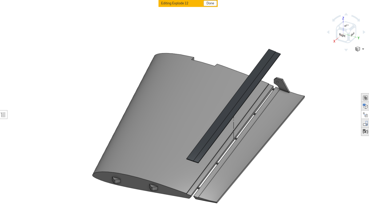
Install the TPU elevon hinge using the same technique described for the ruddervator hinges in BUILD 05.
Start by applying a small bead of superglue to one end of the hinge channel and tack the TPU strip into position.
Once secured, lay the remaining hinge strip into the channel, applying adhesive to the mating surfaces.
Make sure the adhesive reaches the edges of the hinge channel, as these are particularly important for securing the hinge.
Use a damp sponge to press the hinge evenly into position and remove excess adhesive.
Allow the superglue to cure before trimming the excess hinge material from both ends.
Repeat for the opposite wing.
Freeing the Elevons
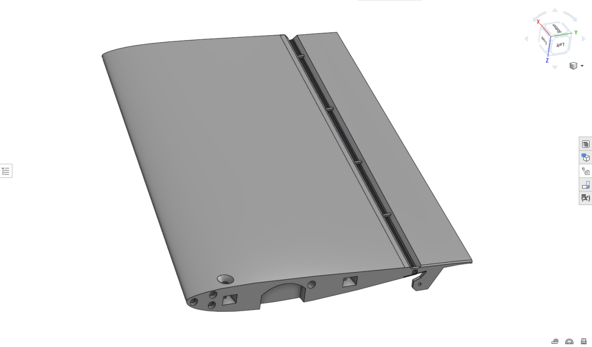
With the TPU elevon hinge installed and fully bonded, the temporary printed connecting tabs can now be removed.
Working from behind the control surface, carefully cut the tabs using a thin razor blade.
Take care not to damage the TPU hinge.
Once the tabs have been removed, check that the elevon moves freely throughout its range of motion.
Remove any excess printed material that could cause rubbing or restrict control surface movement.
Repeat for the opposite wing.
Attaching the Wingtips
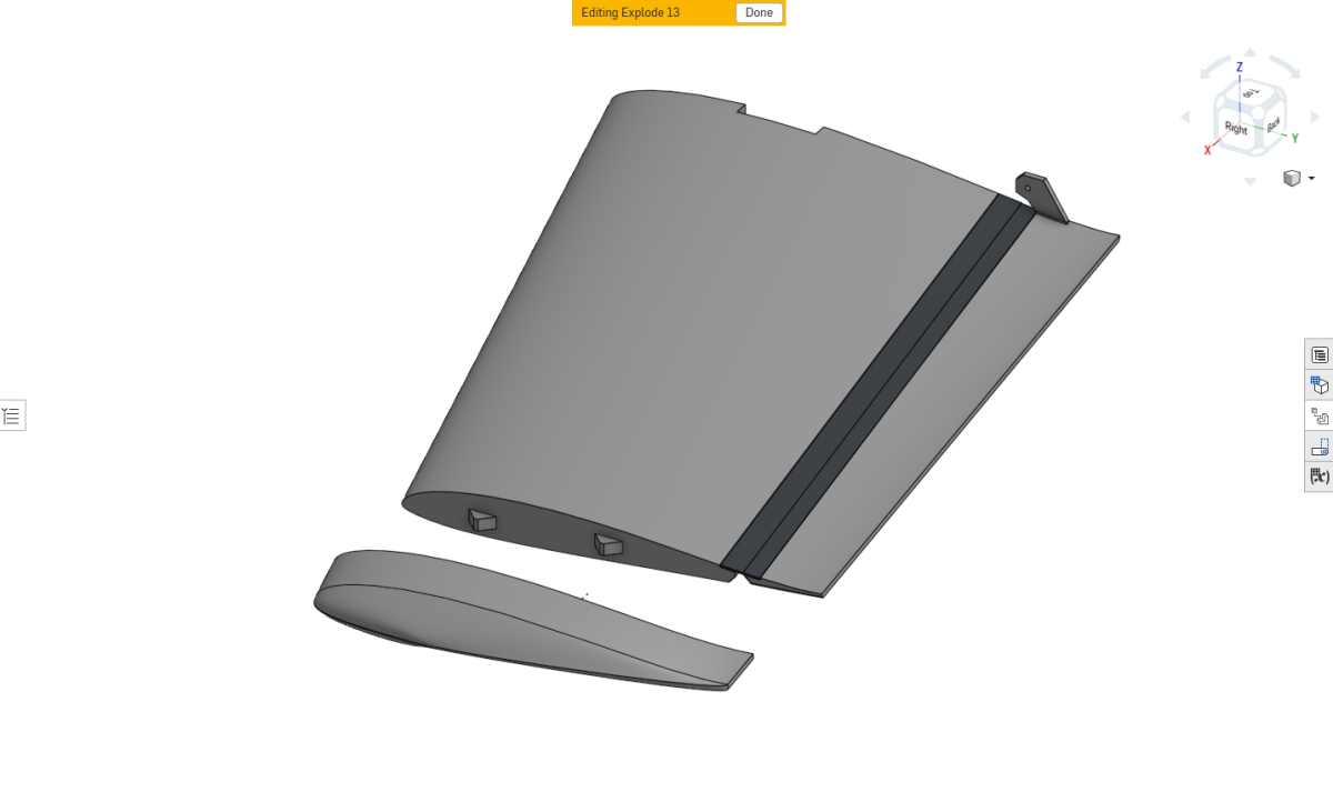
Once the elevons have been freed and their movement checked, attach the wingtips to the outer wing sections.
Make sure the parts are correctly aligned before securing them with superglue.
Repeat for both outer wing sections.
Final Canopy Side Section
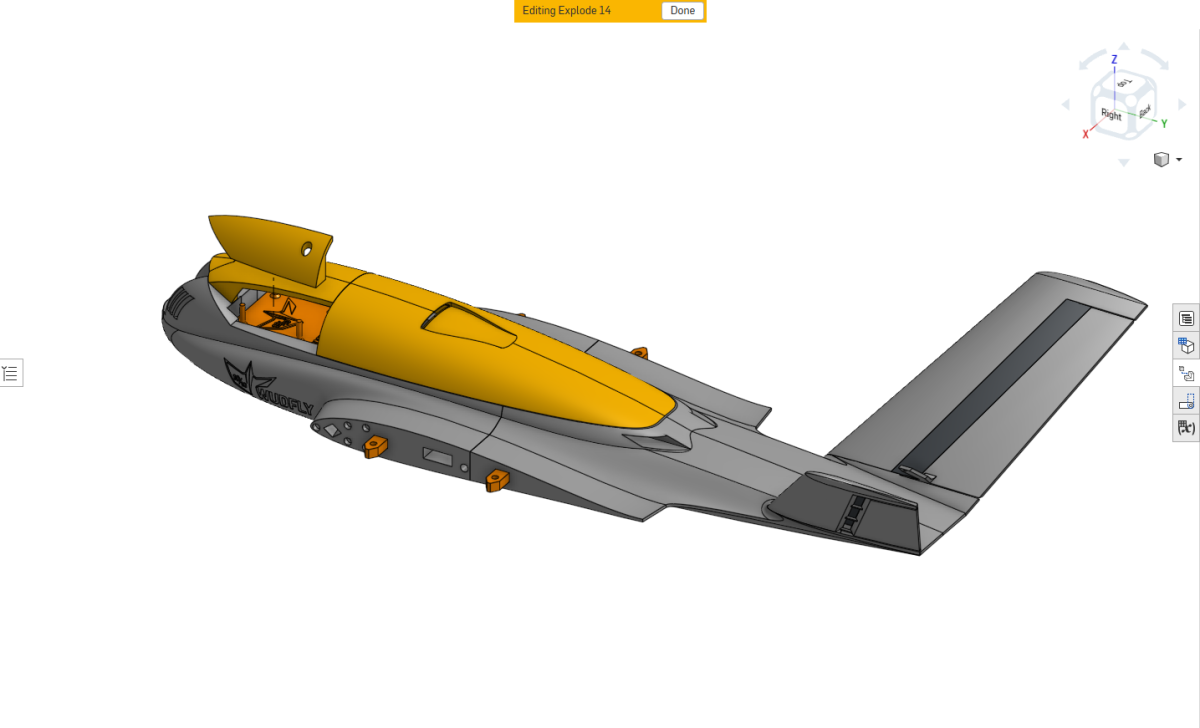
Position the assembled canopy onto the fuselage, allowing the previously installed magnets to hold it in place.
This ensures the canopy sections are correctly aligned with the fuselage.
Apply superglue to the underside of the remaining canopy side section and carefully slide it into position, joining the front and rear canopy sections neatly.
Important: Take care not to allow superglue to reach the fuselage or other unintended mating surfaces. The canopy must remain removable after assembly.
Allow the adhesive to cure before removing the canopy.
Flight Controller Mount
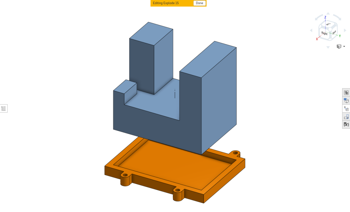
The reference configuration uses the Matek F405-Wing WMO flight controller.
Other supported flight controllers may use different mounting adapters.
Apply a small amount of adhesive to the underside mounting interface of the flight controller and secure it inside its printed adapter, keeping adhesive away from connectors and electronic components.
The adapter remains attached to the flight controller and can be unscrewed and transferred between compatible aircraft.
Before installing the flight electronics, prepare the necessary electrical connections, including the ESC-to-flight-controller wiring and the battery power input.
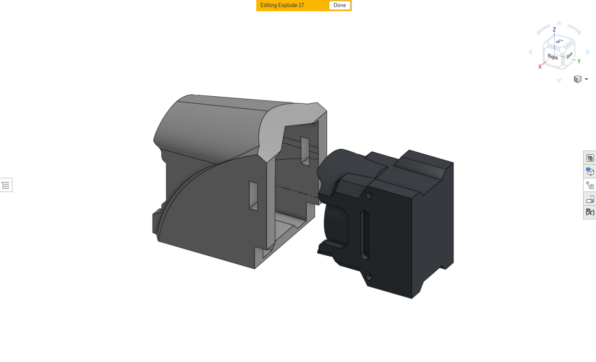
DJI O4 Wide Camera Mount
Install the DJI O4 Wide camera into its printed camera mount.
The camera is retained by a press fit and should slide firmly into position without requiring additional fasteners.
Make sure the camera is fully seated and correctly aligned.
The assembled camera and mount can then be installed alongside the remaining DJI video system components.
Flight Electronics Installation
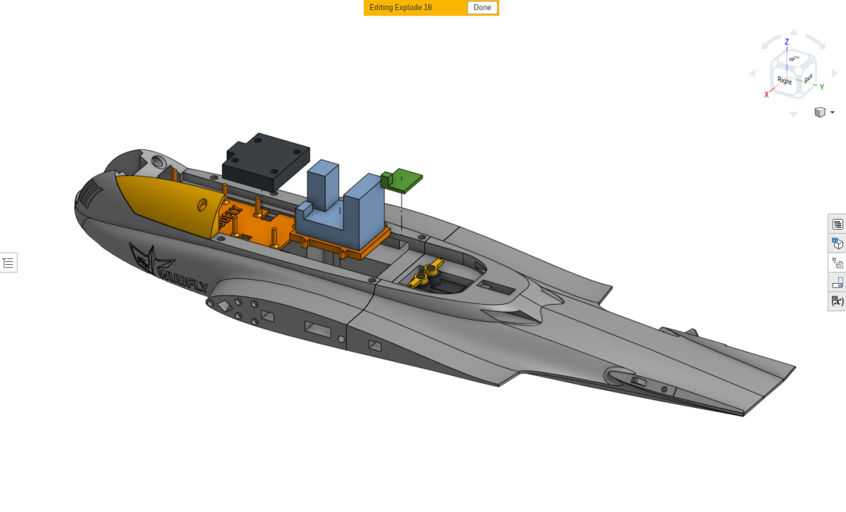
Install the flight controller, ESC and ELRS receiver into the fuselage electronics compartment.
Before installation, the necessary wiring must already be prepared and soldered, including:
- The ESC-to-flight-controller connections.
- The battery power input wiring.
Position the electronics in their designated locations, keeping the wiring organized and clear of the mounting surfaces.
DJI Camera and VTX Installation
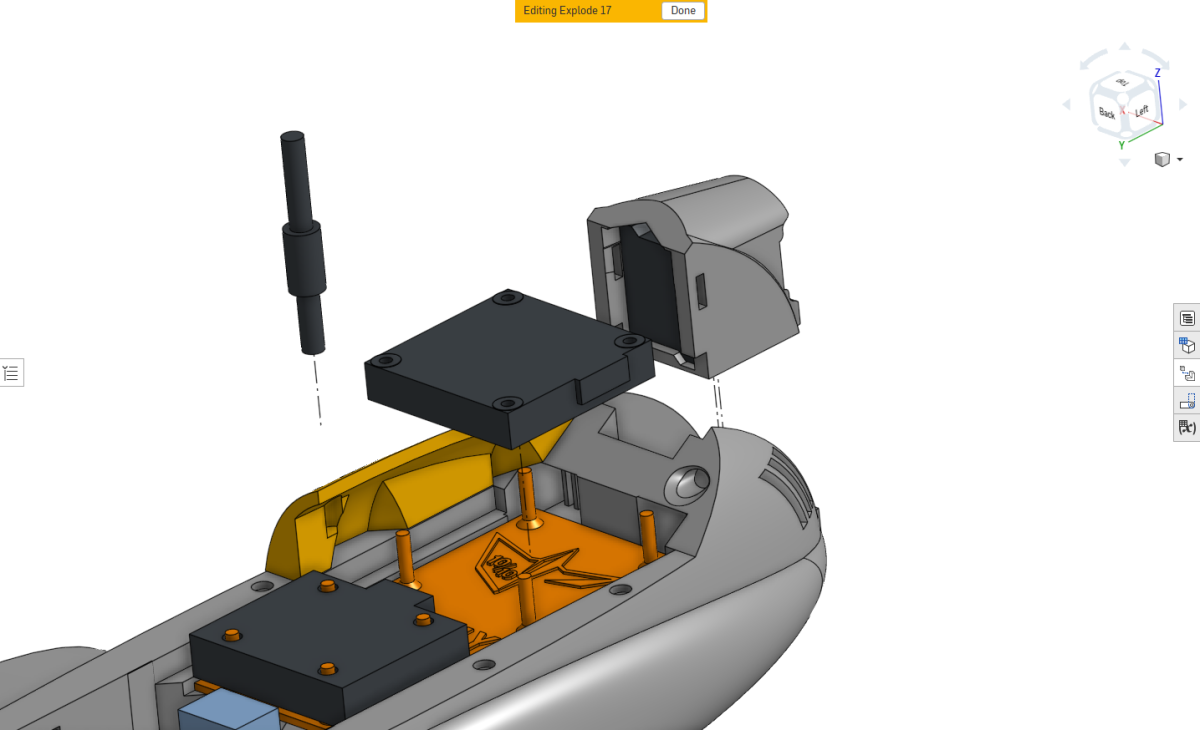
With the camera already fitted to its printed mount, secure the camera mount into the nose of the fuselage using superglue.
Install the DJI O4 Wide video transmitter in its designated position.
Orient the VTX so that its USB port faces the pilot's right-hand side of the aircraft. This maintains access to the USB connector once the system is installed.
Feed the antenna cable through the small antenna opening, passing the cable through first.
Once the cable is correctly routed, connect it to the antenna connector on the DJI board.
Check that the antenna connection is secure and the cable is not trapped or excessively bent.
Inner Wing Installation
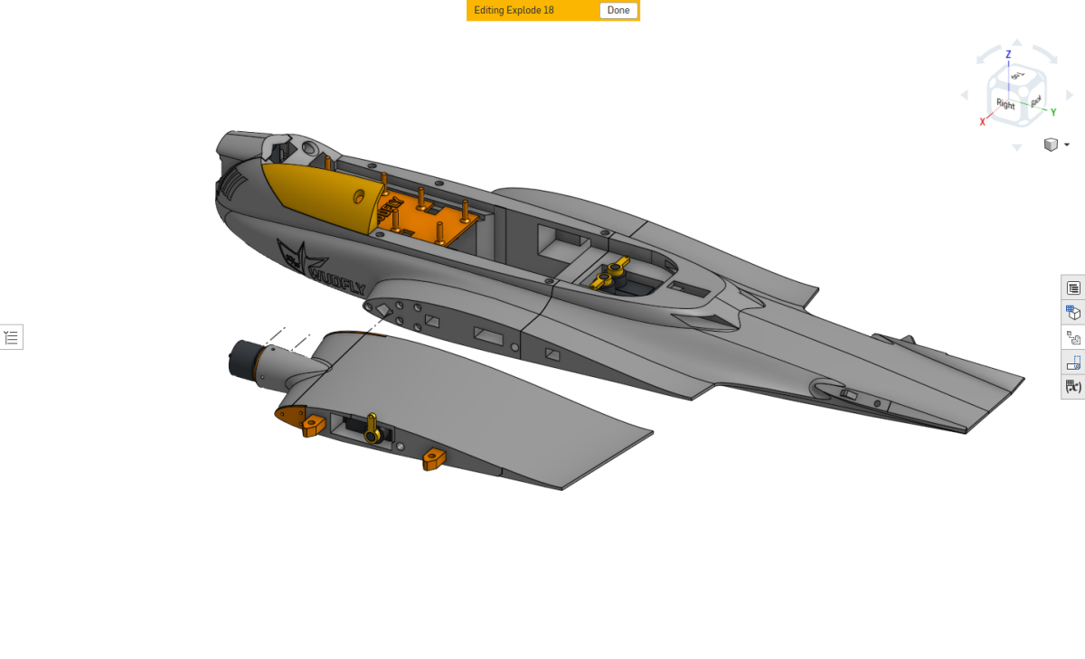
With the inner wing and motor assembly completed, feed the motor wiring through the designated fuselage channel.
Carefully position the inner wing section against the fuselage, keeping the motor wires clear of the mating surfaces.
Attach the inner wing assembly to the fuselage using the previously installed attachment hardware.
Repeat the procedure for the opposite wing.
Motor Wire Routing
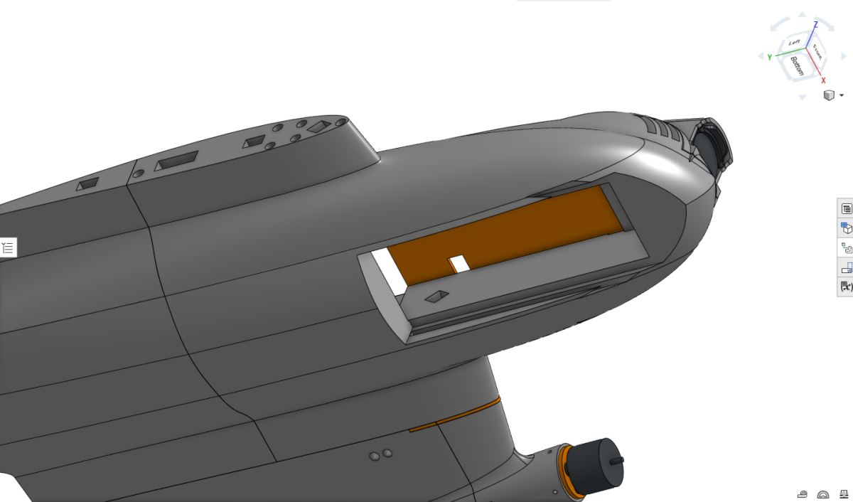
The motor wires should now be visible through the diamond-shaped opening in the fuselage.
Feed the wires upward through the designated opening and into the electronics compartment, positioning them near the ESC for subsequent connection.
Make sure the wires follow the intended routing path and are not pinched by the wing or fuselage structure.
Repeat for both motor wire sets.
Outer Wing Installation
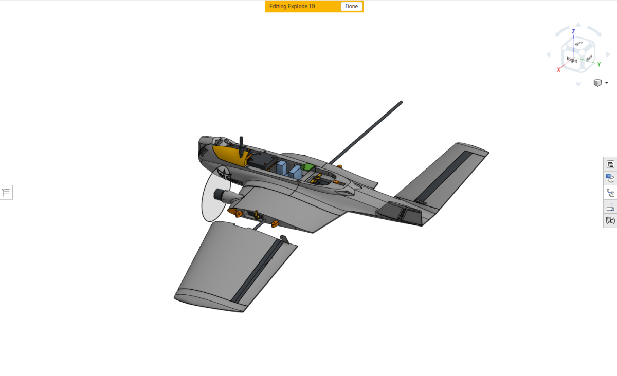
With the inner wing sections, leading-edge assemblies and motors installed, the outer wing sections can now be fitted.
Slide each outer wing section into position, making sure it aligns correctly with the inner wing.
Check that the sections seat properly and that the elevon control surfaces remain free to move.
Repeat on the opposite side.
Before you start wiring.
By the end of the supplied BUILD 24 instructions the wing sections and major electronics should be in position. Check mechanical fit before progressing to the electrical phase.
- Left and right V-tail assemblies are fitted flush and both ruddervators move freely.
- Both TPU ruddervator hinges and both TPU elevon hinges are fully bonded, cured and undamaged.
- Motor cables are routed within their dedicated channels, clear of all wing joints and brackets.
- Both inner wing assemblies are fitted securely and the outer wing sections seat without interference.
- The canopy remains removable, with correct magnet polarity and no accidental adhesive bonds.
- Servo leads, VTX antenna and electronics wiring are free from pinching or unnecessary strain.
Wire.
Reference wiring for the 2S VENOM with twin motors, four servos, a Matek F405-WMO, HAKRC 25A ESC, ELRS receiver and DJI O4 Wide. Adapted from SPECTRE where the components and procedures are shared.
Understand the system first.
VENOM uses the Matek F405-Wing WMO, which has onboard 5 V and servo-power regulation, unlike SPECTRE's external-BEC reference arrangement. The drawing below shows the VENOM component relationships and supported output groups, not a connector-level soldering diagram.
For the board's official pad layout and firmware mapping, see MATEKSYS F405-WMO documentation.
Flight controller power and BEC rails
The Matek F405-WMO has onboard BECs: a regulated 5 V rail for the flight controller/peripherals and a separate Vx servo-power rail. Follow the manufacturer's 5 V / 6 V selection and confirm the installed servo voltage rating before connecting four control servos.
VENOM's reference BOM includes the WMO and a HAKRC 25A ESC, not the external 5 V BEC described in the SPECTRE guide. Do not add SPECTRE's external-BEC arrangement unless a different board and power plan specifically require it.
Connect battery, ESC and flight-controller power according to the official Matek diagram. Ensure grounds are common and never connect conflicting regulated BEC outputs together.
Set the wire lengths in the aircraft
Dry-fit the Matek FC, HAKRC ESC, DJI O4 Wide VTX, receiver and battery inside VENOM before cutting any leads. Check fit with the removable canopy in place.
Route the motor leads through the inner-wing and leading-edge channels and then upward through the diamond-shaped fuselage openings as described in BUILD 22–23. Keep wires out of the wing mating surfaces and removable fastening areas.
Leave enough slack for service and wing removal, but avoid loops that obstruct the battery or control linkages.
Connect the main power system
The reference battery is a 2S LiHV 1000 mAh pack using an XT30-type connection. Prepare the battery-positive and negative wiring to the ESC and F405-WMO power-distribution connections using the appropriate pads on your specific board.
The BOM includes AWG18 battery-to-ESC wiring and an AWG18 FC-to-ESC connection. Verify the actual electrical function of each lead from the official diagrams before soldering.
Motor phase wires and rotation
Connect the three phase wires from each VCI Spark 1103 11000KV motor to one ESC motor channel. Use the routes described in BUILD 11, 13, 22 and 23, without pinching the motor wires beneath the leading-edge brackets or the removable wings.
VENOM uses two motor channels: left and right. Confirm which ESC output corresponds to the pilot's left and right motors in the actual VENOM mixer before selecting or fitting propellers.
Motor direction can usually be reversed in compatible ESC configuration software without resoldering the phase wires. Verify the correct VENOM propeller rotation from the approved setup.
Connect ESC motor signals to the Matek WMO
The Matek F405-WMO exposes S1 and S2 as motor outputs in its standard INAV Plane/VTOL mapping. Run the two independent control signals from these outputs to the selected motor inputs of the HAKRC 25A 4-in-1 ESC.
Wire the signal grounds according to the ESC's actual input requirements, and do not assume that a SPECTRE Flywoo ESC signal harness has the same pin order as the HAKRC. The ESC protocol must also be compatible with the installed ESC firmware.
Connect all four control servos
VENOM has four servos: one for each elevon and one for each V-tail ruddervator. The F405-WMO's standard INAV output group reserves S5, S6, S7 and S8 for servo control, separate from the motor S1/S2 group.
Connect each servo's power, ground and signal to the appropriate regulated servo-output circuit. The left/right elevon and ruddervator assignment must match the validated VENOM CLI; the S5–S8 group alone does not establish the order.
Keep the ruddervator wires routed through their rear fuselage channels and ensure no cable can interfere with a moving horn or linkage.
Connect the ELRS receiver
The reference VENOM build uses a RadioMaster RP1 ELRS receiver. The Matek F405-WMO has CRSF-capable UART connections; the official documentation identifies TX2/RX2 as one supported pair.
Supply the receiver with the correct voltage and common ground. Connect receiver TX to the flight-controller RX and receiver RX to the corresponding flight-controller TX. Confirm the final UART selection in INAV Ports and the supplied VENOM CLI.
Route the receiver antenna so it cannot be pinched by the canopy, V-tail mounting hardware or servo linkages.
Connect DJI O4 Wide video system
The DJI O4 Wide camera connects to its matching DJI VTX using the supplied camera cable. VENOM's VTX is oriented with the USB port facing the pilot's right, as described in BUILD 21.
Use the official DJI and Matek references to confirm the VTX power-supply voltage and any serial/MSP connection required for your chosen OSD setup. Route the antenna cable through the prescribed fuselage opening and attach it securely.
Before first power-up.
Work through these VENOM checks before connecting the battery. The F405-WMO's internal BEC and four-servo arrangement differ from the SPECTRE reference.
- Battery polarity, ESC and Matek WMO power connections match the actual hardware diagrams.
- FC 5 V and servo Vx power rails are correctly configured for the connected devices.
- No two regulated BEC outputs are unintentionally connected in parallel.
- ESC receives two independent motor control signals and a valid common reference/ground.
- Four control servos are connected to outputs whose mapping matches the VENOM setup.
- ELRS receiver TX and RX are correctly crossed with the selected FC UART.
- DJI O4 Wide VTX has the right supply voltage and a securely attached antenna.
- Both motor wire bundles are clear of all modular wing joins and fasteners.
- V-tail servo wires and linkages move freely without chafing.
- All propellers are removed before configuration and motor tests.
Built to come apart again.
Like SPECTRE, VENOM is designed around serviceable, removable wing modules. The motor wire channels, PETG WingLoc hardware and carbon wing structure are all intended to make component replacement easier.
Before removing a wing assembly, disconnect wiring that would otherwise be strained, then remove the correct nylon fasteners. Never pull a wing against attached motor or servo leads. Electrical plug and solder arrangements depend on the completed reference installation.
Configure.
Install and configure INAV for the Matek F405-WMO, verify the VENOM-specific mixer, calibrate the aircraft and check all six motor/servo functions before fitting propellers.
Start from the VENOM setup.
VENOM requires its own INAV CLI configuration for the Matek F405-WMO, its four control servos and V-tail/elevon mixer. A SPECTRE CLI is not compatible as a direct substitute.
The final VENOM release CLI will establish the tested motor and servo assignments, transmitter input conventions, control mixing and rate settings. Record the firmware version alongside the CLI, and check each setting after loading it.
Install INAV Configurator

Start by installing INAV Configurator on your computer. It is the official cross-platform configuration application for INAV and is available for Windows, macOS and Linux.
Download it from the official INAV Configurator release page: Official INAV Configurator download .
The current official INAV documentation is also available here: Official INAV documentation .
If INAV is not already on the board
The VENOM reference build uses the Matek F405-WMO.Matek F405-WMO. If your board arrives running another firmware such as ArduPilot, INAV must be flashed before the VENOM CLI can be loaded.
The standard INAV flashing workflow is: connect the flight controller by USB, open Firmware Flasher, select the correct board/target and firmware, then flash the board. INAV's own installation guide recommends using Full Chip Erase when INAV is being flashed to a board for the first time.
Board-specific flashing details can vary, so check the documentation supplied with your flight controller before flashing if the target or bootloader procedure is unclear.
Load the supplied CLI
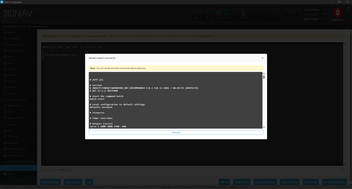
When the VENOM-specific CLI becomes available with the aircraft download, use the matching firmware release and connect to INAV Configurator.
Open CLI → Load from File, select the VENOM file, review the loaded commands and choose Execute. Reconnect and confirm that no commands were rejected.
If there is no validated VENOM CLI in your download, do not load the SPECTRE configuration. The four-servo V-tail mixer and output routing are different.
Calibrate the flight controller
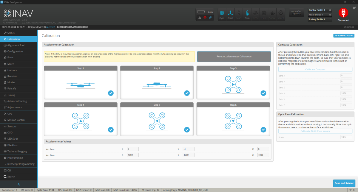
Loading the supplied CLI does not replace the normal INAV board calibration. The accelerometer calibration belongs to your individual flight controller and must be completed after the board is installed in the aircraft.
Open the Calibration page in INAV Configurator and work through the accelerometer routine shown above. Place the aircraft in each orientation requested by INAV and allow each position to register before moving to the next one.
Take your time with this step. The aircraft should be held steadily on each face so INAV can establish the board axes accurately.
When the calibration is complete, return the aircraft to its normal flying attitude on a level surface. The aircraft shown in INAV should agree with the real model: when VENOM is level, INAV should also report it as level.
Enable the motor and servo outputs
In INAV, verify that the two motor outputs and four servo outputs are enabled on the Matek F405-WMO and match the VENOM reference mixer.
For this board's standard mapping, S1/S2 are the motor group and S5–S8 are the four-servo group. The left/right assignments and control mixing must come from VENOM's tested configuration, not an assumed channel order.
Select an ESC protocol actually supported by the installed HAKRC ESC and firmware. SPECTRE's DShot300 setting is a useful reference but is not automatically a verified VENOM setting.
Check motor direction
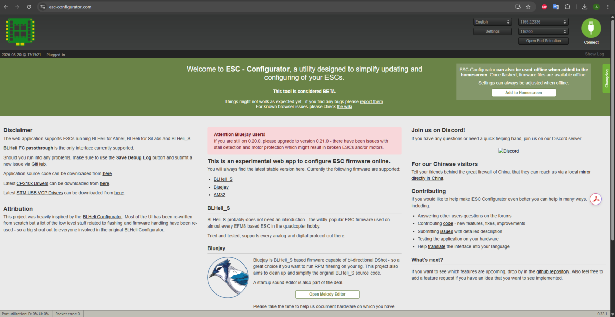
With the propellers removed, connect to a compatible ESC configuration utility and test the two VENOM motor channels at low output. Verify the channel-to-motor relationship and the direction of rotation.
Use the VENOM propeller and mixer reference to determine which direction each motor must spin. If needed, reverse the ESC rotation setting and retest. Do not rely on SPECTRE's propeller direction without checking the VENOM setup.
Save settings and verify both motors once more before fitting the propellers.
Before the propellers go on.
Complete the following VENOM-specific checks with the aircraft powered, propellers removed and moving linkages clear of hands and wiring.
- INAV is installed on the Matek F405-WMO and the firmware target/version are correct.
- The validated VENOM CLI has been loaded without rejected commands.
- Accelerometer calibration is complete; INAV agrees with the physical aircraft attitude.
- Two motor outputs and four servo outputs are mapped and correctly enabled.
- ELRS responds to transmitter commands, and receiver failsafe is configured.
- Pitch, roll and yaw commands move the intended elevons and ruddervators in the correct directions.
- Stabilization correction directions have been checked for all three axes.
- All four linkages have full, unobstructed throw and secure horns.
- Motor assignments, rotation and propeller orientation have been confirmed against the VENOM setup.
- Battery is retained securely; removable wings and V-tail are firmly attached.
- CG, surface neutrals, throws and flight modes match the validated release documentation.
What remains to confirm.
The PRINT and BUILD text is now populated from the supplied VENOM source material. These items are marked rather than guessed so the next revision can be checked against the aircraft and released files.
Artwork revisions
Correct the PRINT 14 PETG plate image; check BUILD 14–16 illustrations against their operations; confirm BUILD 20 electronics figure.
Hardware cross-check
Confirm the exact printable motor-mount component names, ruddervator pushrod diameter, final motor-mount screws and V-tail carbon rod fit before release.
Wire chapter
Supply the verified Matek WMO, ESC, four-servo, DJI O4 Wide and ELRS wiring diagram, power rails and pin assignments.
Configure chapter
Publish the validated VENOM CLI, INAV firmware version, motor rotation, neutral throws and CG references.